If you have done your homework, you should understand how it's wired up by now. Nevermind, here are some photos to help you.
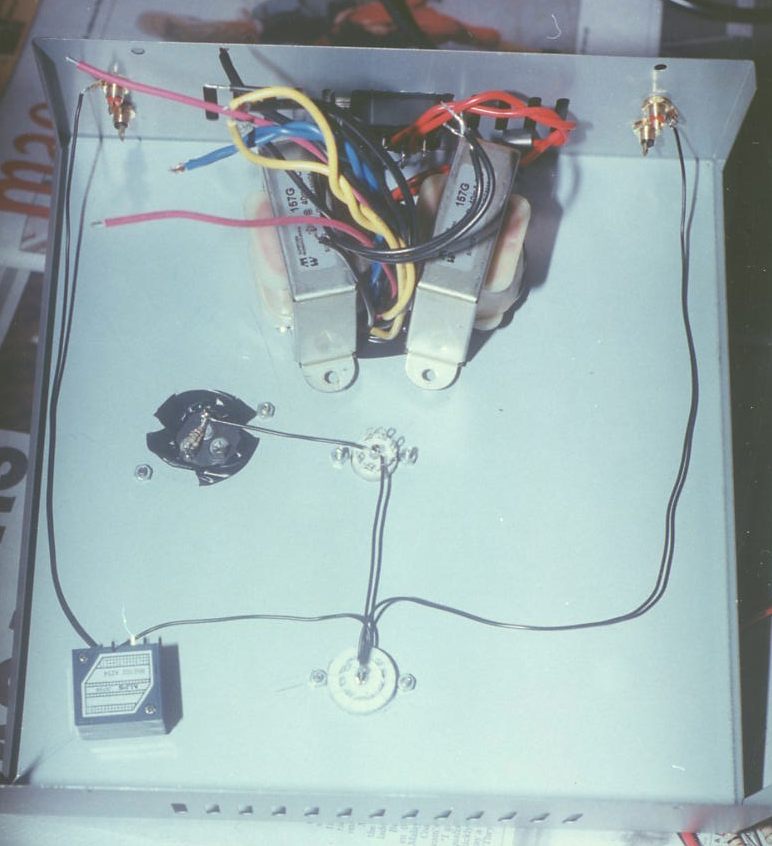
You start by laying out the ground path. I used the same wire as the rest here, but you could opt for the better option of using thick copper, say awg 12. A good and cheap option is those copper rods used for gas welding, available from your local hardware store.
Here, the filament wires have been wired. This is simple as there's only 2 tubes to consider. Note that I have wired 5687 heaters in PARALLEL. That means shorting pins 4 & 5 and wiring heater to 8 and 5. All filament '0' tap refered to ground.
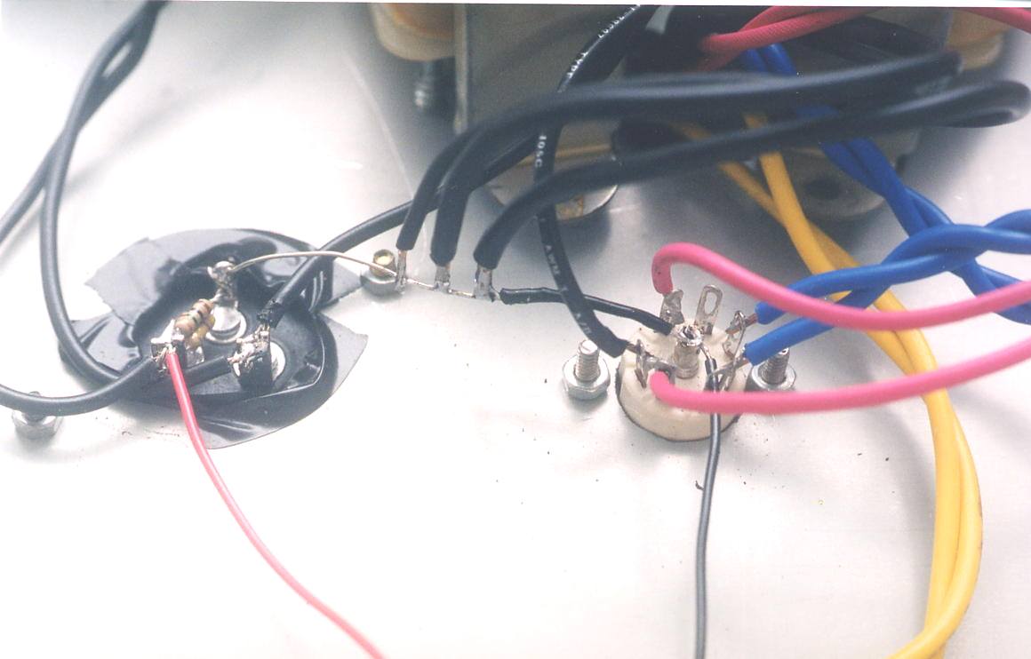
Next, I wired up the power supply section. It's easy with this double capacitor. The pink wires are 350V. The red wire coming out from the capacitor is my B+. Note that I have wired in a resistor on the capacitor. This goes from +ve to Gnd. This is a bleeder resistor, meant to discharge your capacitor's charge, lest it discharges on YOU with dire (some find it fun though) consequences. Aim to bleed about 1mA, so for B+ of ~280VDC, a bleeder resistor of 270kohm/2W is fine.
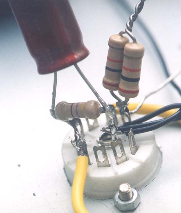
Ahem, signal circuitry. Remember signal circuitry consists of only 2 resistors? One on the plate and one on the cathode? Here the plate resistor is a paralled combo of two 20kohm 2W resistor to give me a 10kohm 4W resistor. The cathode resistor is 470ohm, paralleled with a 470uF electrolytic. It's better if I could place the electrolytic lower but this makes it easier for modifications later. Being DIYers, this is important! Err, shown here is only signal circuitry for Left channel. Yellow wire is for filament heater.
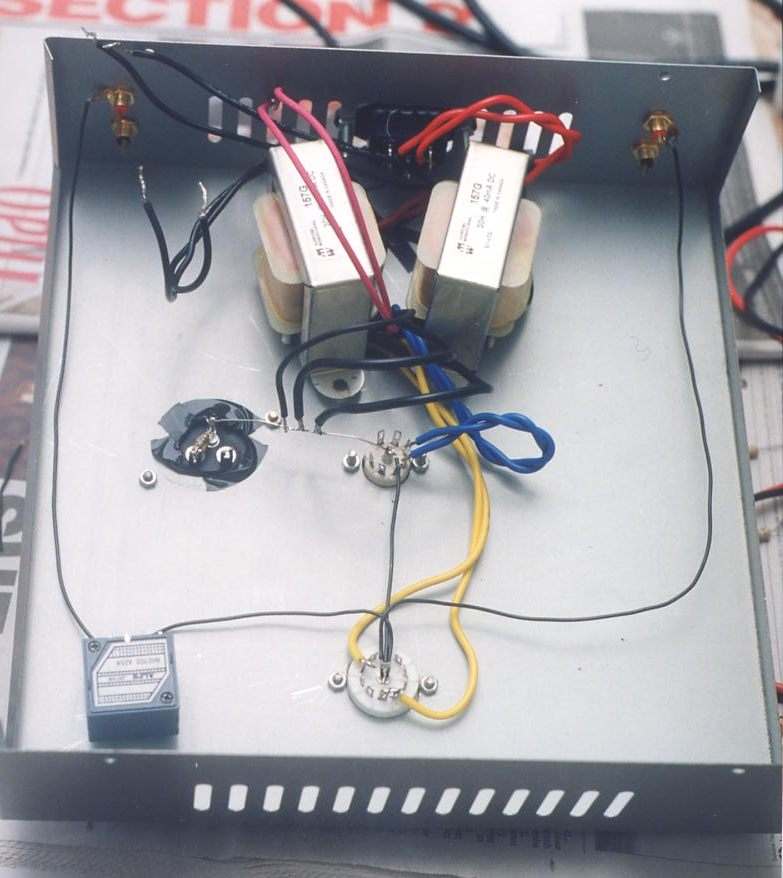
While you are enjoying the pictures (and waiting eternally for them to download...), I have finished wiring up the other channel! Click for higher resolution (and more waiting) picture.

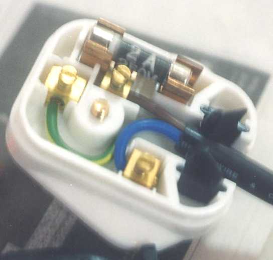
Okay, the urgency to power on is high now but hang on! First thing first, before you plug in your IEC cable, change the fuse in the plug to a lower current rating. I have 2A here as I can't find 0.5A. Preamps don't need high current so 0.5A is good enough. The last thing you want is for some fault to occur and your nicely built preamp go up to smoke just because the current isn't high enough to break the 13A fuse. You have been forewarned!
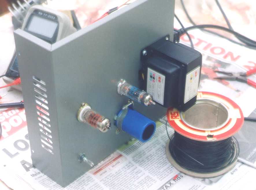
Another use of a wire spool... This way, I could test the voltage points with a multimeter. It's important to make sure voltages are correct within 10% tolerance before plugging into your system. Check with voltage points on the schematics.
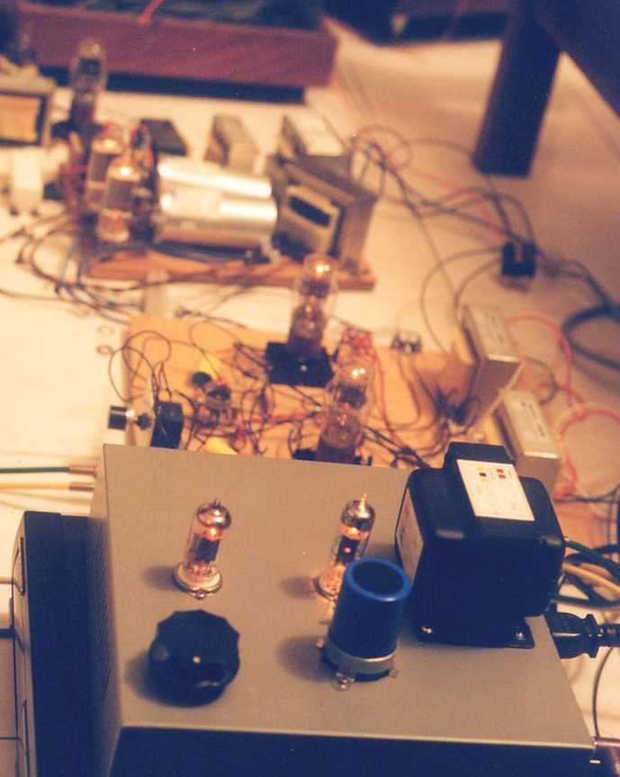
Finito! Bathed in warm light as well! No wonder it sounds warm?

Plays music with the rest of the system. It worked right the first time!
There you have it! Hope you enjoyed the music, err the ride. Sorry for the long download time.
Done yet? Not yet! Go to Options page ala Part 3.