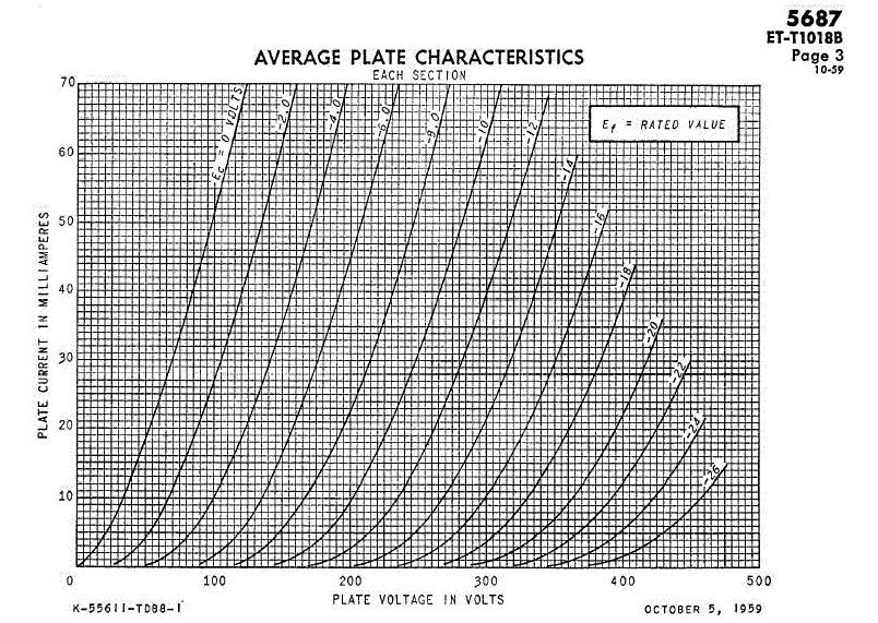
Have you ever wonder, faced with a graph of Volts and Currents, how does a "circuit designer" choose a point to operate his tube? How does he/she lock into the operating point of the tube that could give maximum sonic ecstasy? How does he determine the plate/cathode/grid resistors/voltages/current?
Well, wonder no more! As your's truly is going to show you "a day in the life" of a BOGUS "circuit designer".
7am. Yup, early riser. Early bird gets the worm, remember? Pity the early worm...
8.02am. Download emails, read depressing world news. Stomach growls. Nothing like "viagra-like" "teh tarik" (frothy milked tea that's addictive...) and decadent breakfast (nasi lemak) to start off the day!
10.16am. Damn! How time flies! Let's start work. But first, turn on system first... Waittttt a minute. Imaging was better yesterday. What happened? Checked here and there, but couldn't figure out! Ah! When girlfriend tidied up house last night, she accidentally moved the speakers an inch out of its optimized position (yeah, like my system is so sensitive...).
11.23am. Oh shit! Time really flies! Now music is playing, we are in the mood to get started. Begin by staring at the curves of the 5687 tube as it's a pretty popular tube among Diyers. Also, if you have built the Simple 5687, maybe after reading this, you can start to "screw around". The tube curves, that is!

After squinting your eyes for so long, do you hear the music? Probably not, so let's get started. First off, Let's choose a B+. Now if you are modifying a preamp/poweramp, you might already have a B+, but if you are designing from scratch, it's easier to go for a relatively low/safe B+. I like best B+ <400V, as you can still use standard caps. Caps with ratings above 500V are a real pain in the wallet. So let's start off with B+ of 260V.
Now that we have settled on the B+, we need a plate load. A resistor of some magnitude. Typically for triodes, we want to load it many times its plate resistance. 5687 has a plate resistance of ~2kohm so if we load it 5x, this means a plate resistor of 10kohm. Alright!
We can start to draw the line now. A tube load line is straight and to draw a straight line you need 2 points right? If you look at the above curves, it's a Current versus Voltage graph. More accurately, it's a Plate Current versus Plate Voltage graph. Easiest way to start will be to plot the 2 points where Plate Current is zero and Plate Voltage is zero.
Point #1. Plate Current is zero. This means NO CURRENT at all flowing through the tube. The only way this is possible is that the Plate Voltage is at B+, cos this means there is no voltage drop across the plate resistor, hence zero current. So we have found one point! Please mark at graph, I=0mA, V=260V. Not bad progress for a morning. : )
Point #2. Plate Voltage is zero. This means MAX CURRENT flowing through the tube! Wow! I definitely won't want to run my tube like this. Now, to have max current flowing through, the only way is the plate voltage is at zero volt. It's like saying the tube has shorted itself to ground, so we have a short circuit where between B+ and GND, the only resistor we have is the plate resistor of 10kohm. We need to do some really difficult maths here so please bear with me. Now, Mr Ohm said that VDropAcrossResistor = CurrentThruIt * Resistance. So we now have 260V = Current * 10kohm. Current should therefore be 260V/10kohm = 26mA. Phew! Tough maths is over. Now we have another point. I=26mA, V=0V. Now mark these 2 points and draw a straight line.
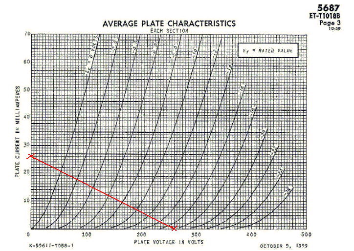
If you are still with me up till now, pat yourself on your back! As it's time for lunch! Now you probably don't realize the significance of all this, but your BOGUS "circuit designer" is happy with the thought that he is already controlling the operation of the tube. You see, if built into a circuit with said B+ and plate load resistor, your plate current/voltage can only be along this straight line. Yes, it can't sway to any point it likes, it has to be along this straight line. Think of the infinitesimal plate current/voltage combo that is possible, and you have now forced (coerced?) the tube to operate just along this straight line. How about that? Aren't you please? As I've showed you, it's easier to ask a tube to walk a straight line than yours truly here after 5 shots of Jack Daniels...
1.46pm. Oops! Lunch is over. Now we want to get into specifics. We know our tube will walk ONLY on this straight line, so we want it to sit quietly at the best point, of least distortion, of max sonics ecstasy. Hee hee... Now look at the curves again with the drawn load line. It intersects the grid curves from 0V to -16V. Asking it to sit quietly at one point is actually asking it to sit at the point at zero signal. This is important as your signal is going to be positive and negative, so it'll swing up and down this straight line. If it sits at -14V, it can't swing more than 2V negative though it could swing 14V positive. Nah, we don't want this. It's like you are sitting on a bench where 2 lines of beautiful girls will sit beside you. To get the max out of this (oh yeah!), you will want to sit preferably a position where you can have 5 beautiful girls on your left and 5 more on your right. This way you can engage in witty repartee with all 10 and shower them your charms. You are not very charming nor bright to begin with, if you sit at the very far end with 1 girl on your right and 9 more on your left. Perhaps you want to concentrate on one girl, but it's okay to be greedy here. I allow you this.
So, let's choose -6V as we can have 8 beauties on the right and 6 more on the left. We are not going to pay attention to the last 2 beauties on the right as as you get to -14V and -16V, they look "compressed". Not very pretty after all. (If you think I'm a male chauvinist pig, sub the above beauties with hunks of your choice.) So -6V it is. Now, mark this point on the curve.
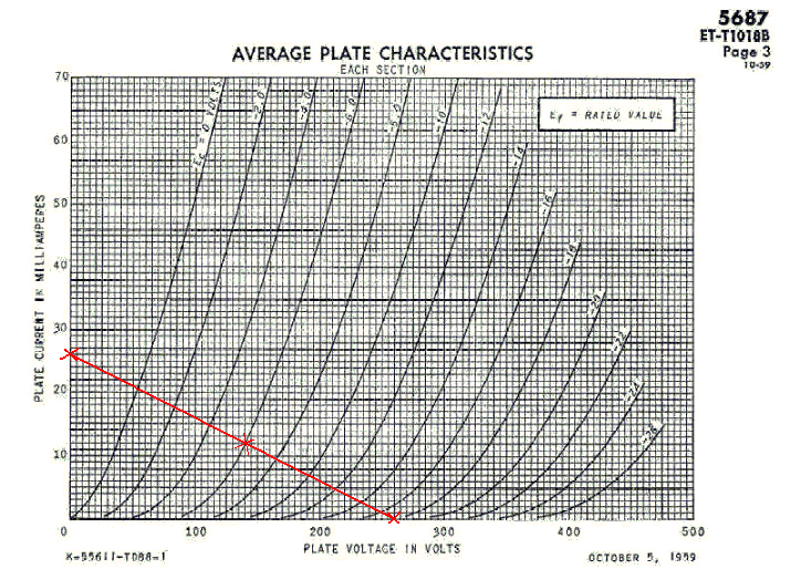
We are smoking now! We have chosen a point which looks pretty even up and down the grid line. The grid now sits at -6V so when signal comes in, it'll be swinging up and down -6V along this line. If you look closely, the lines are pretty evenly spaced out, so linearity is good, distortion is low. If you are mathematically inclined, you can proceed to calculate how much distortion is there. But since I'm such a BOGUS designer, I'll pass this step.
What the operating point also tells you is that, you are now ready to build the circuit! You now have B+ of 260V, plate resistor of 10kohm, what's missing is cathode resistor. This is easy. At -6V grid, you are going to get ~12mA. Back to Mr Ohm... R = VDropAcrossResistor/Current = 6V/12mA = 500ohm. Choose the nearest 470ohm for simplicity's sake.
You can build the circuit now! The curves also tell you one thing. If you build the circuit, you will get grid of -6V, plate current of 12mA, and plate voltage of ~130-140V. So you got to measure this on your physical real-world circuit. If you measure something remarkably different, then you screwed up somewhere along the line (I love the pun...).
3.30pm. Starts looking for parts. Fortunately have a ready supply of 250V. Just need to bump it up a little to 260V. Actually, it should be okay with 250V too...
4.59pm. Finally have all parts! Oh dear, it's almost 5...
7.26pm. Finally wired up everything. Going to power it up but tummy is staging a protest. Damn! Spirit is willing but flesh is weak, so let's eat.
8.42pm. Finally powered it up! Voltages are close enough. See schematic. The curves predicted the voltages and currents, and it's pretty close! Any deviation is best to blame the tolerance of resistors, tolerance of incoming VAC and also the weather. : ) Just don't blame the designer, okay?
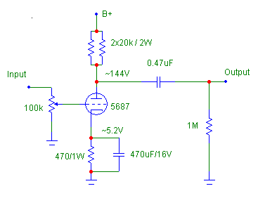
Time flies when you are having fun, but Kermit the Frog said, "Time's fun when you are having flies". And now only the fun begins. The above is the first step to get started. Then comes the listening test cause as good as curves are, they are just... curves. You still need to listen to how it performs. After listening, and gauging its performance, we'll try another point. Try a different cathode resistor, or different plate load. Redraw the curves if necessary. Try another B+ if necessary.
1.12am. After trying various operating points, the first is the best. Ah! The benefits of hindsight. But I hope you now understand how all this works.
If you read "Variations of the Same Theme", sometimes the point where the curves look horrible sound better! Therefore it's worthwhile to experiment. Hey, just because the last 2 girls look "compressed" doesn't mean they are horrible girls okay? Give them a chance.
In case, if you wonder why -6V grid but we are measuring 6V on cathode? It's because there's a 100kohm resistor at the grid, so the grid is actually sitting at 0V. So if cathode goes 6V, then grid-cathode voltage is -6V. Understand this, the tube doesn't see anything outside, it just sees things reference to its terminals, so it only understands plate-cathode voltage, grid-cathode voltage. Therefore you can build the Simple 5687 to sit at 100V cathode, with 94V at grid and 360V plate. It'll still give you 12mA through.
Lastly, will like to point out that this BOGUS designer didn't design the Simple 5687. It's designed by Mr. VT4C, but I'm just taking it to show you how the points are arrived. Now you know why I'm BOGUS?
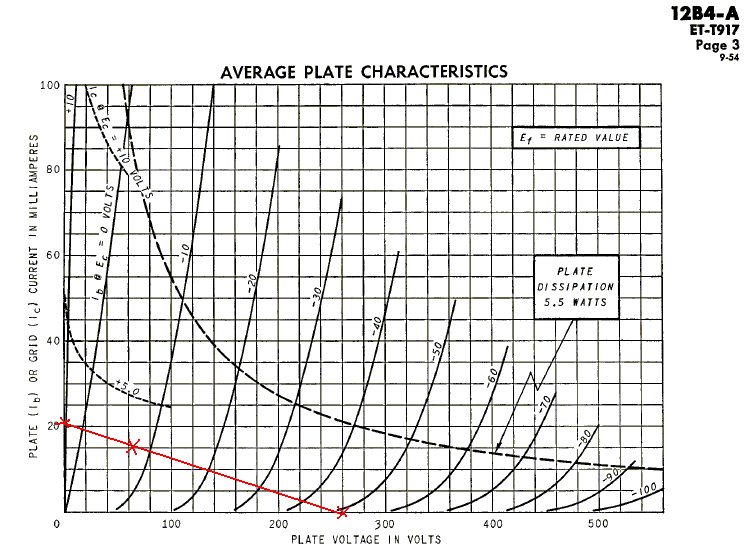
Here is the curves for 12B4 and loadline for the "Etude" preamp. Note that the grids are spaced 10V apart. This is with B+ of 260V, plate of 12kohm and cathode of 470ohm. I got about ~7V for the grid which will be hard to estimate from the curves. Now this curve also shows you "Plate Dissipation". Whichever operating point you choose, make sure it doesn't stray beyond this curve. Make sure that all points are to the left and below this curve. A short tube lifetime is only a tube reseller's idea of fun, okay? Err, why at 7V when there are so many points to choose from? Since this is a linestage, it won't see more than 3V incoming signal, so it's still okay. Adapt it to your system.
Now that you can start to be a circuit designer (hopefully not bogus like me), do understand there are various philosophies regarding its sonics. Some designers like to run the tubes hot, very near it's plate dissipation. Some like high voltage, low current, while some prefer low voltage, high current. Sometimes when designing, you are aiming for maximum voltage swing, hopefully not at the expense of linearity.
Philosophies. The list is endless, and the above, by no means, is exhaustive. There are other parameters to take care of like plate resistance, amplification factor, subsequent stage etc but I sincerely hope that you can start to experiment with tube operating points. Very often, the change in operating point yield a MUCH MUCH BIGGER improvement than boutique parts. Try it.