What is the easiest, cheapest way of trying out non-oversampling?
Non-Oversampling DAC project
What is the easiest, cheapest way of trying out non-oversampling?
If you can trace the I2S signal in your CD player, tap it, fit in a TDA1541 (and attendent signal gain circuitry), then you have it!
You save a chassis, an interconnect cable and have the shortest signal path. What more can you ask for? Furthermore, it saves you lots of unnecessary circuitry in between. Imagine, I2S gets converted to SPDIF, then converted back to I2S… Why go through all this trouble? Why not just tap the I2S straight off? You save an expensive CS8412, you save a lot of unneccessary headache.
With the Marantz CD63 service manual, I think I have found the I2S signal.
If I’m not mistaken, signals WCLK, SCLK and DATA constitute the I2S format.
Wiring to a TDA1541 is easy and it’s only these 3 signals. However, due to the sin(x)/x filter, many builders of the non-oversamping DAC hear a marked loss of high frequency energy. Reason being, the DAC starts to roll off at 10kHz and at 20kHz, it’s already down 3dB. Hardly great stuffs huh? It’s even worse on my Hammer Dynamics as the treble is already laidback, putting down another 3dB isn’t pretty…
To get back the 3dB lost at 20kHz, a simple LC resonant filter will do. Thorsten Loesch has pointed the way in using the TDA1543. With YH’s help, I have adapted one for the 1541.
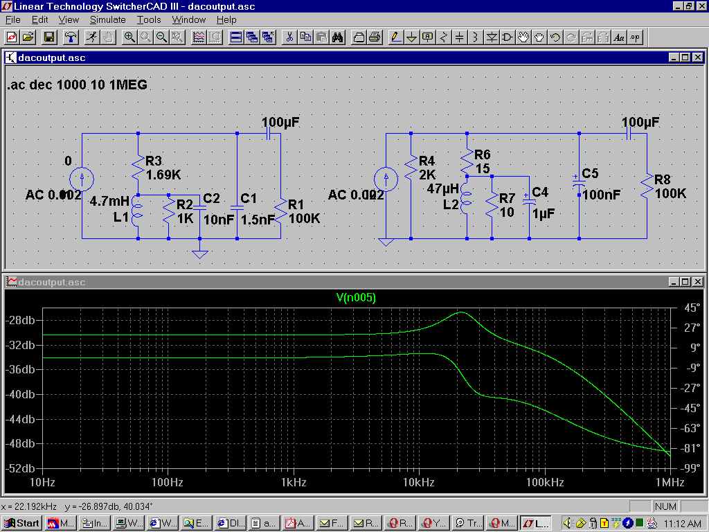
The circuit on the left is Thorsten’s for TDA1543. The right is my adaptation for TDA1541. The simulation has 2 traces. The top trace is the frequency response. Note that it gradually rises and reaches a peak of about 3dB at ~20kHz. Phase shift is about 10 degrees at 20kHz.
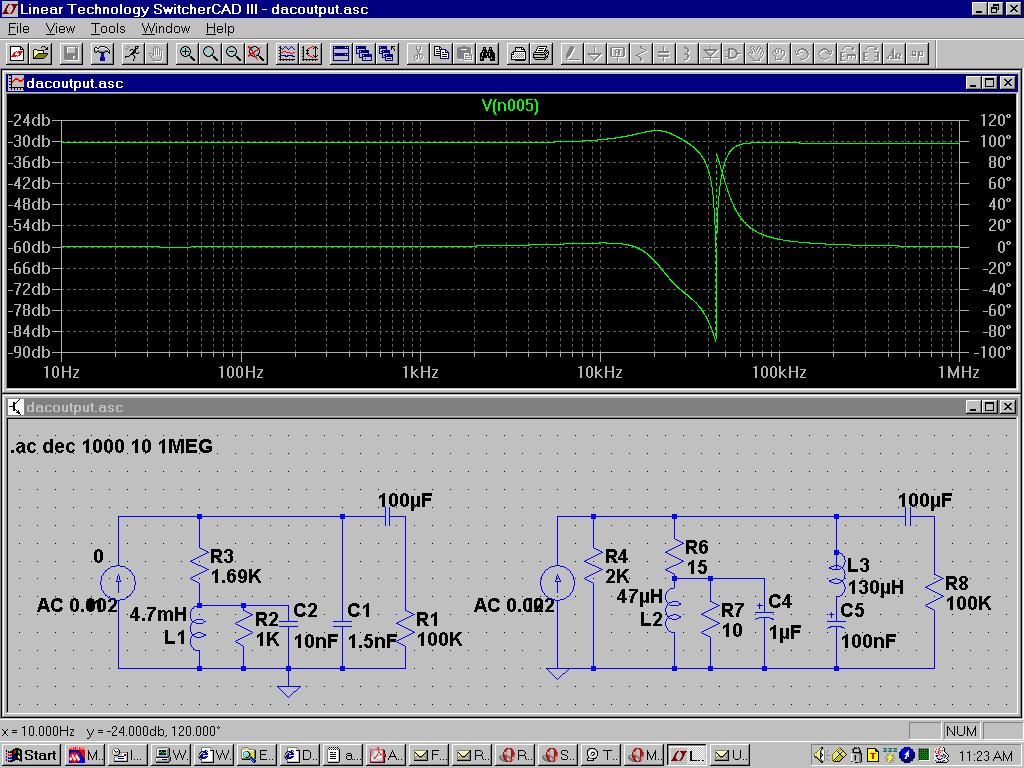
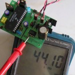
This is even better! (Thanks YH!) A notch filter is added to filter out the 44.1kHz CD sampling frequency. The wild swing on the phase plot is expected, courtesy of the notch filter. The 2 inductors in the circuit can be hand wound, then adjusted (add/reduce windings/ferrite) until “right”.
Do realize that the above is all just circuit simulation. When you build this circuit with real world components, all hell breaks loose. Stray inductance and stray capacitance will make their prescence felt. Imperfect components (is there any perfect component?) will make matters worse. Oh well, live with it…
Anyhow, you need to add a gain stage to amplify this signal. The output is only ~20mV at the node between the 100uF capacitor and 100kohm resistor, so a gain of 100x is needed to reach full output of 2V. Fill in your choice of gain stage, op amp or tubes. You can, of course, add another stage of RC filtering after your gain stage to reduce any output after 20kHz. The choice is yours.
That’s all to it! Again, there’s nothing new here. Stole some ideas here and there, and got the above. Thanks to buddy YH for his ideas.
Simulation was performed using Linear Technology’s excellent SwitcherCAD.
Are you ready to build one? I just did the above with a TDA1543. A non-oversampling DAC for < RM20.


No Responses