"Yeo, I want to build the circuits on your projects page but you only show signal circuitry but no power supply circuitry."
Err, you are right.
An amplifier is basically a modulated power supply, so the power supply circuitry should get your utmost attention, then only followed by the signal circuitry, not the other way round. I have built a few different versions so I could tell you more about each of them, with some example circuits you could try yourselves. As always, take everything you read with many grains of audiophile salt, me included. The circuits shown on this page has been simulated using the excellent Power Supply Designer.
Okay, here goes.

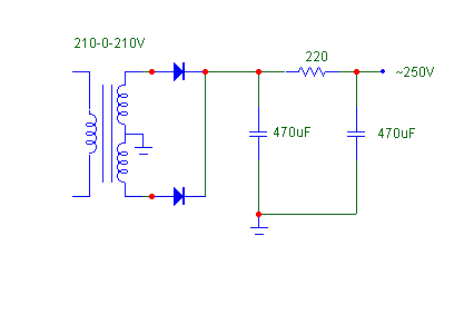
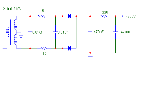
The above is a basic "brute force" method. Least in cost and bulk. For the diode, use whatever super-fast, soft-recovery, hexfred blah blah blah as see fit. To improve on it without spending too much, sandwich a snubber circuit in. Snubber circuit courtesy of John Camille from Bottlehead.

To make it even better, you could opt to swap the 220ohm resistor with a choke. Any choke with DCR (DC resistance) ~200 ohm would do.
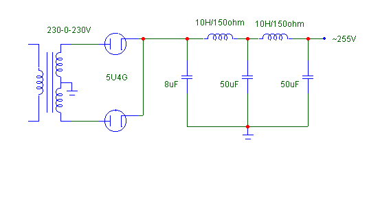
Use a tube rectifier! Kinder to tubes, they don't leap to full B+ at turn on, but I don't welcome the added expense, and the voltage drop.

The above uses tube rectifier and is 2-stage filtering. If you prefer to remove one stage, remember to compensate with more capacitance. If you replace one choke with a resistor, you need to increase the capacitance too. The above uses 5U4G but if you wish to try something else, go ahead. Just simulate it with the Power Supply Designer.
If you don't want to spend too much on tube rectifiers, since NOS versions could cost a bomb, use TV damper diode like I did! They are BIG, they can handle lots of voltage and lots of current and they are CHEAP. Read this.
You could play around with the sound by adding more capacitance, say use 100uf instead of 50uf but be careful with the first cap right after the tube rectifiers. Lots of them don't like high capacitance. The 5U4G don't like more than 20uF.
I could think of 2 conventional power supply filters. Choke input and capacitor input. I find that choke input is quieter, but capacitor input seems to be more dynamic, albeit noisier. Choose whichever you are comfortable with.
You could hear what you put in the power supply circuitry. I like chokes. Presence of chokes smoothen the mids and highs, deepen the lows but at a loss of speed. The Presentation seems to be more relaxed, slower. Kenneth once told me he likes the bass of cap input but prefers the mids/highs of choke input. There you go.
Electrolytic capacitors get a lot of flak for its sonic characteristics. Well, we live in a real world where, unfortunately, cost per micro-farad is the lowest for electrolytics. Elna Cerafine and Black Gates are raved as the best sounding electrolytics but the prices is too high for a cheapskate like me.
Okay, my approach to good sounding, not too expensive power supply circuitry is this. I like lots of chokes and very little capacitance. When you don't have lots of capacitance, you really need lots of chokes. Unfortunately, this makes your amp really heavy. Chokes are cheaper than quality capacitors.
Unfortunately as well, you don't see lots of chokes in commercial designs. This makes the amp too heavy. Nor do you see the usage of oil capacitors in the power supply. The combination of chokes and oil capacitors make a VERY heavy power supply. My power supply is heavier than my signal circuitry.
Alright, consider this. My Darling amp originally uses "cheap, cheap, cheap" as shown above. Diodes, resistors and 2 very high capacitance capacitors. RCA tubes sound musical but thin and compressed. The GE 5 star beats it by a mile.
Then I rebuilt my Darling with an extra-mojo power supply. Lots of chokes and lots of oil caps. This time, the difference between the RCA and the GE 5 star is subtle. Not day and night like before. Huh? I couldn't believe it!
So, before you pay expensive moolah for NOS tubes, consider uprading your power supply. You may be in for a treat.