Ever wonder how your favourite capacitor stack up against the competition?
Dare to compare!
Sure you must have read all those glowing reports
about this component, that cap blah blah blah. Ever wonder how true are those
claims? Ever wonder whether it’s really worth paying all the $$ for these
“wonder” parts?
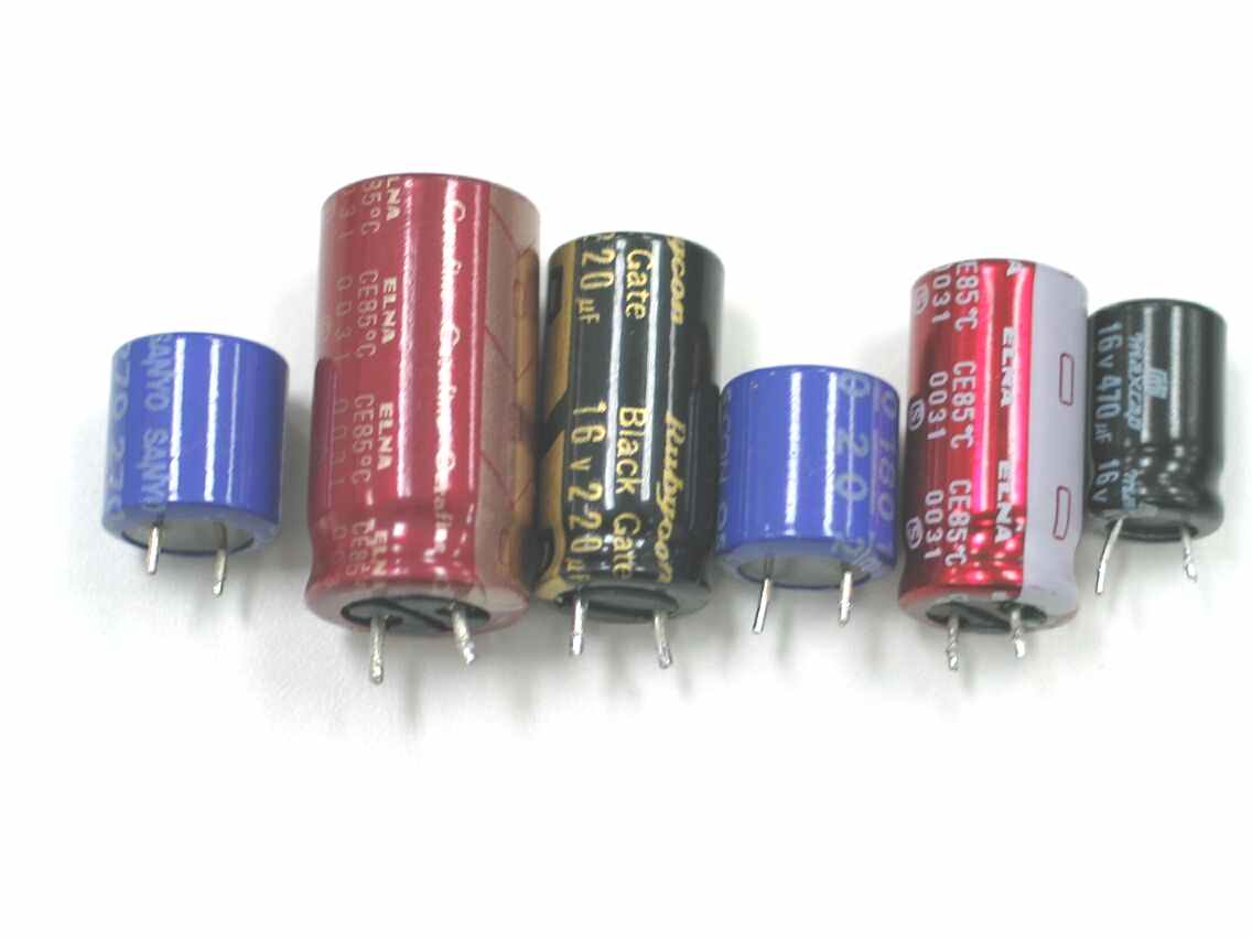
Have no fret! As DIY Paradise just completed a
simple shootout between electrolytic capacitors. The target here is in the use
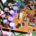
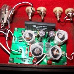
in power supply decoupling. Test circuit as below. Pulse drives the base of the
2N3904 transistor and 2 points are monitored. The blue bubble labeled
“scope green trace” and the red bubble labeled “scope yellow
trace”. If an ideal capacitor exists, then the capacitor under test will
not show any ripple at all due to transistor switching on and off.
Credit for test circuit goes to YH and Thomas.
Test setup is a pain. At such high frequencies, even a few mm lead length will throw the whole thing off! I actually did this test twice. First time was done “on air”, I just soldered the transistors to the caps. Results were very inconsistent, and not repeatable as well. Something must be wrong. Reason being the lead length of the caps were different and they were quite “far” from the transistor. How “far”? A few mm off! I revisited the setup. This time, using a breadboard. The caps and transistor were soldered on the board. I trimmed off the leads of the caps and pushed them down on the board, so that they sit snugly. I’m sure the lead lengths (and distance between cap to transistor) are equal this way. To change caps, I have to desolder them off. As you can see, it’s really a pain going through all this.
And the results! If you are too lazy (or impatient) to look at these plots, go to summary page.
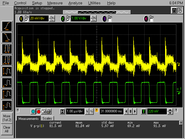
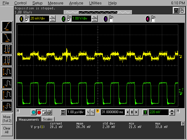
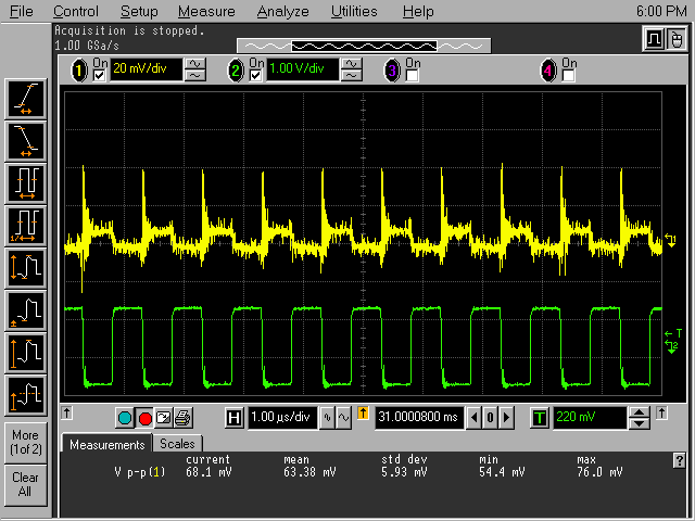
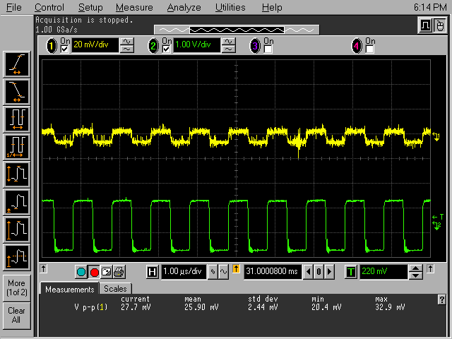
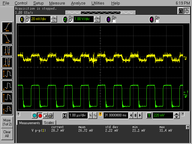
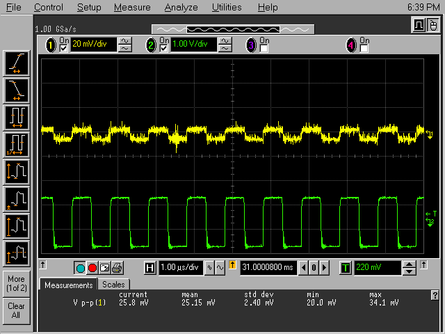
1MHz pulse
Generic “Max” electrolytic. 470uF 16V.
Ripple of 81mV is measured.
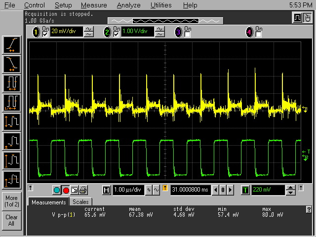
Elna Starget, 470uF 16V. Ripple 67mV.
Elna Cerafine, 470uF 25V. 26mV.
Black Gates, 220uF 16V. 63mV.
Sanyo Oscon. 180uF 20V. 25mV.
Sanyo Oscon. 270uF 16V. 27mV.
Sanyo Oscon. 470uF 10V. 26mV.
Dare to compare Part 2!
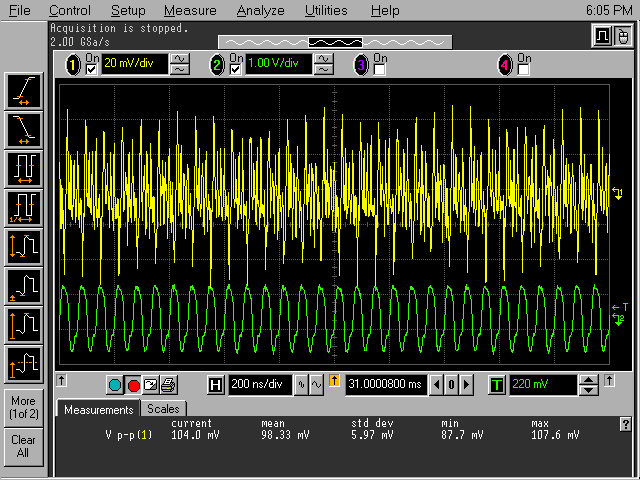
15MHz pulse
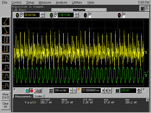
Generic “Max” electrolytic. 470uF 16V.
Ripple of 98mV is measured.
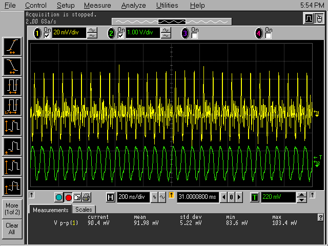
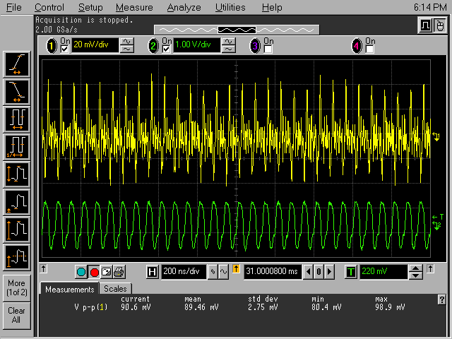
Elna Starget, 470uF 16V. Ripple 90mV.
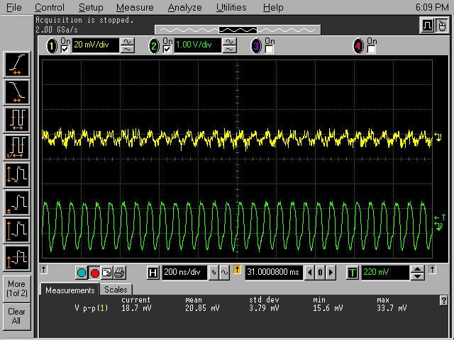
Elna Cerafine, 470uF 25V. 20mV.
Black Gates, 220uF 16V. 96mV.
Sanyo Oscon. 180uF 20V. 90mV.
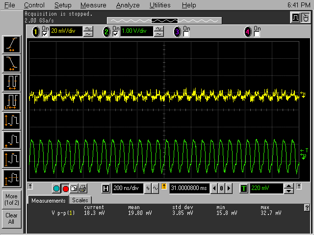
Sanyo Oscon. 270uF 16V. 20mV.
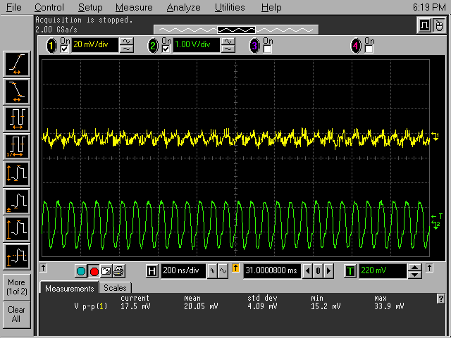
Sanyo Oscon. 470uF 10V. 19mV.
Whoa! What does this tell you?
Some comments from YH:
The square waves show spikes with some caps and no spikes with others. The ones with no spikes are to be much preferred. This means the BG can be considered non-audiophile approved for decoupling.
For spikes, you hv to look at the spectrum analysis of the output sq waves with the caps. The ones with least noise is best. I believe you can easily switch to spec analy mode on the scope.
Some comments from vt4c:
Perhaps the Black Gates need longer break-in?
Some comments from Thorsten Loesch:
I’d note that all the premium capacitors show a notably lower noise level (including even the Starget which really are no good above around 100KHz and are designed and made for low audio range distortion) than “generic” ones. Even the BG and worse looking Os-Cons show at 1MHz only the initial inductive spike but an overall much lower noise level. As ANY of these capacitors require further bypassing in high speed applications, using the right ceramic bypass would eliminate the spike. In addition, the 15MHz curves would look much cleaner, 15MHz is really crapshooting in the dark with electrlytics.
What I would say is that, it’s EXTREMELY difficult to redo this test after breaking-in each cap for say, 300 hours. It’ll take more than a month! That said, you can see why some caps are great in digital circuits and some are just crap.
To do better, for the technically inclined (and those great with the soldering iron), Thorsten has this to suggest:
> > It would be interesting if you could test equally a
> “tripplet” consisting > 1pcs 10nF 0805 X7R SMD Capacitor,
> 1pcs 100nF 0805 Z5U/Y5U SMD Capacitor > a SH Series Os-Con
> 10uF/6.3V (with 5V supply) plus a further 1,000uF
> > Panasonic FC capacitor.
>
> i don’t have these capacitors.
Then MAYBE you should get some. The SMD ceramic Cap’s are DIRT CHEAP (strip >of 100pcs for a buck or two), the Sanyo Os Con and Panasonic FC are pretty generic parts too with generic industrial prices.
I mention this arrangement as if you test it you will find the noise much lower even at much higher test frequencies than any of those capacitors you tested.
As you seem to modify and build a lot of Digital gear I’d just like to note that strategically placement of suchlike SMD Cap combos plus the Os-Con give a PSU node impedance that is almost non-reactive at the driven node point (sadly IC lead inductance somewhat spoils the very good effect) around 0.5 Ohm up to 30MHz (towards DC it’s a question of how good your regulator is) and remains below 1 Ohm until way above 100MHz. The result is considerably better sonically AND in measurement than the sum of the parts and by far ahead of just fitting some fancy “boutique” capacitors.
More goodies suggested by YH:
3-terminal feedthru caps from Murata…
OK. Why the hell am I taking the trouble doing all this? It’s meant to show you that, next time before you spend your big $$ on stuffs, know what you are buying. There’s a marked difference between the capacitors above. The test was done at “clock frequencies”, thus the best capacitor suited for such function is the Sanyo Oscon. You can definitely do better by following what Thorsten and YH suggested but pay particular attention to your layout, otherwise it’s all moot.
For DIYers, if you build a clock circuit and it doesn’t sound good, refrain from blaming the circuit. An oscilloscope tells the best story (of course, not everyone can afford them) but the plots shown here is a guide.
Next time I see some digital circuitry with generic caps, I’ll duck! : )

No Responses