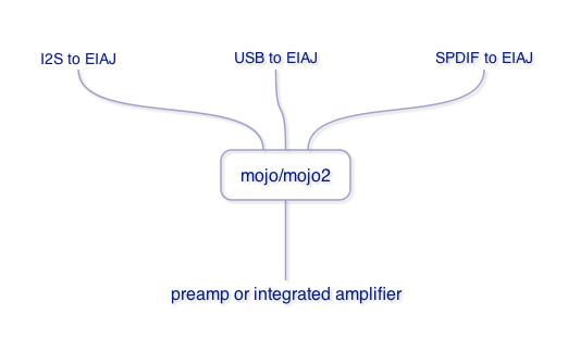
Every system needs some mojo… For Monica, here’s the best mojo she could get now. From the roots of Rudolf Broertjes’ SS I/V Gain Stage, with the help of intrepid diyers, modders on the diyers forum, we now present you…. mojo!

mojo will be as a kit for now.
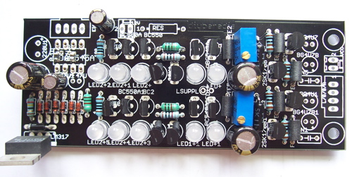
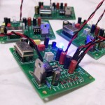
As you could see, I fancy black solder mask and silver plated PCBs these days. Looks and sounds awesome. Hee hee.
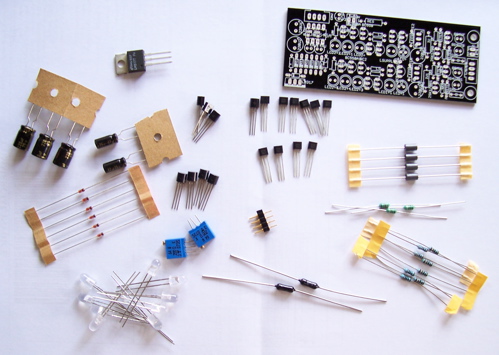
Parts List
24 Ohm Resistor x2
100 Ohm Resistor x2
820 Ohm Resistor x2
1000 Ohm Resistor x4
Takman 1/2W 5600 Ohm I/V Resistor x2 WOW!
Ferrite bead x6
1mH inductor x3
1N4148 Diodes x6
1N4007 Protection Diode x1
LM317 x1
Panasonic 47uF FM x2
Panasonic 220uF FM x3
200 Ohm Trim pot x2
Low Noise Red LED x10
Toshiba 2SK170 FET x4 WOW!
BF245C x2
BF245A x2
ZTX651 x6 WOW!
ZTX751 x4 WOW!
4-pin header pin
Notice that the ultra-low profile sockets and those excellent 0.1uF Panasonic film caps have already been soldered in for you. All together now….WOW!!!!!!
Assembling mojo
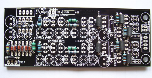
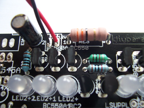
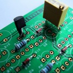
With mojo, first thing to do is to solder in the low-lying components – resistors, inductors and ferrite beads. From left to right, the resistors are 24ohm, 2 pcs of 100 ohm, 2 pcs of 820 ohm and lastly 4 pcs of 1kohm resistors at the far right end. The inductors are all 1mH.
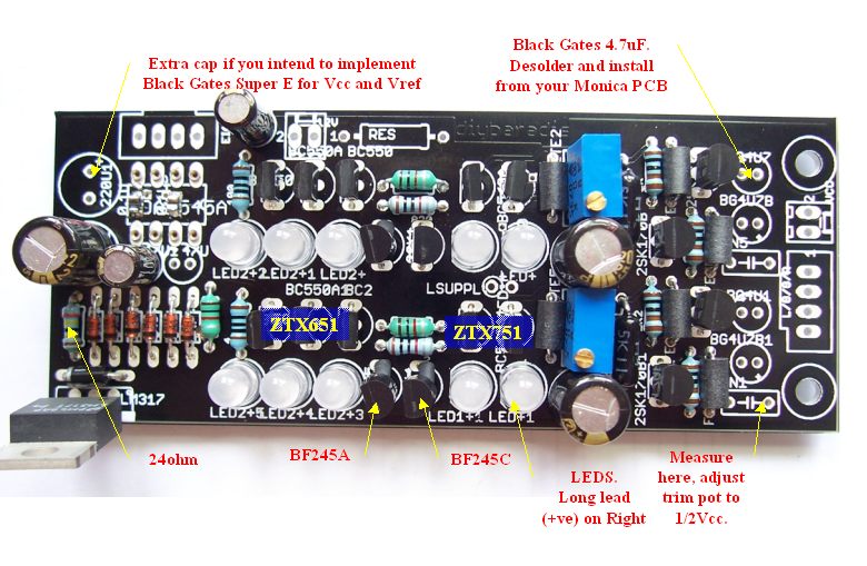
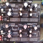
And now you solder in the transistors. From Right to Left, 4 pcs of 2SK170, 4 pcs of ZTX751 and 6 pcs of ZTX651. The cascaded FET CCS we should come to it in a moment. Leave it blank for now. All transistors and FETS are to be installed such that they can be read nicely as viewed from the Left side, meaning viewing from the string of 1N4148 diodes end.
Update on 15th March 2009. New PCB corrects this already, so no “transistor cross legging” required.
Here is the painful part. This PCB’s cascaded FET section was designed for 2SK170 but this has now been ditched for BF245x which have a different Gate and Source pintouts. As such, I’ll have to trouble you to cross the legs of the FETs and protect them from shorting through heatshrink tubings. The FETS are 2 pcs of BF245C and 2 pcs of BF245A.
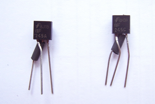
Now you could solder in the FETs. Note location of BF245C and BF245A. If you place them in the other way, the circuit will still work, but you’ll always have a niggling doubt as to whether this circuit could be further optimized. And it could! If you place these FETs in the prefered location.
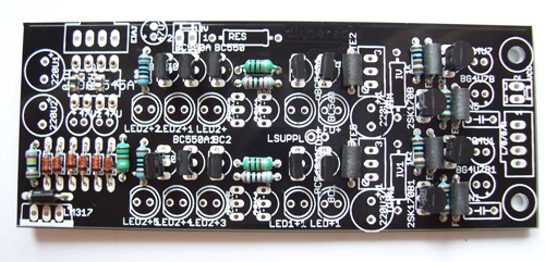
Stuff the electrolytic caps, the LEDs (all have the same orientation) and trim pot.
Here’s another guide.
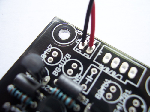
Power supply wiring is shown here. 15-24VDC, entirely up to you.
Customization
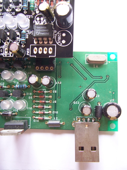
Here, I leave this entirely up to you to customize your mojo as everyone has different needs, so too with mojo! The resistor marked “RES” you could use this to drop voltage between the I/V stage and the TDA1545 circuitry. Shown here is a metal oxide 2W 33ohm resistor. Alternatively you could leave out this resistor and utilize the power supply connections beside to separately power your TDA1545 circuitry. Hey, whatever tickles your fancy ok?
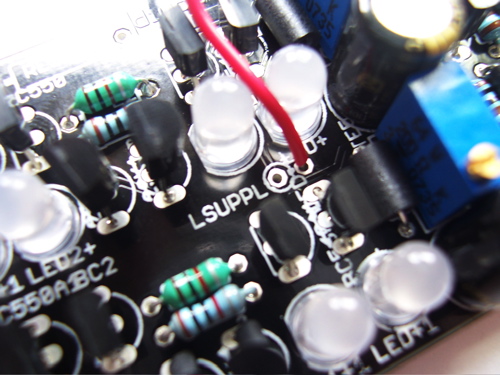
If you feel like powering the SS I/V Left/Right channels with different power supplies, I’m certainly not going to stop you! Simply supply a separate VCC to “LSUPPLY” as shown. However, both channels will share the same ground. Should you desire to have the same supply for both channels, then just put a jumper on “LSUPPLY”.
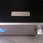
Giving Monica some mojo!
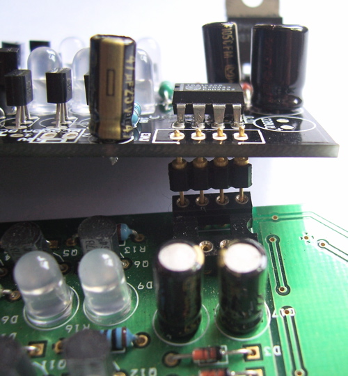
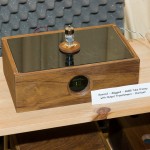
Shown here is mojo being “mated” with USB Monica. Remove the TDA1545 chip from USB Monica, transfer to mojo PCB and plug in this double sided header pins. Note that one end of the header pins have larger plugs than the other. The larger one goes to mojo while the smaller one plugs into existing EIAJ conections (pins 1-4 of TDA1545). If you reverse this header pin, it won’t fit.
USB Monica, given some mojo, will sing for you even better than before!
Update on 15th March 2009. Mojo kits purchased on 15th March and onwards require no rework on your part.
Corrections on the PCB
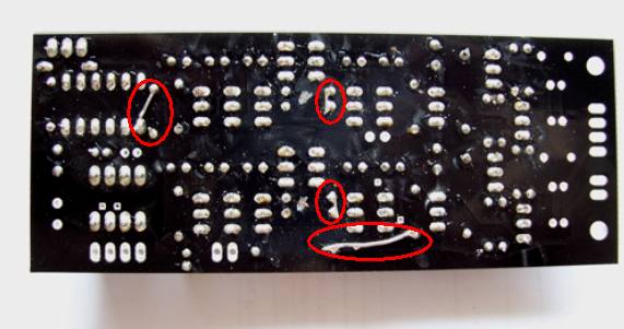
I’m known as a klutz. I’m also hopeless at proof reading. So despite many attempts, I still made mistakes on the PCB. Here I rely on your grace to correct them on my behalf. Actually I corrected some. Places where the trace has to be cut, I have cut them with this cool PCB drill I just bought… Now you need to apply these jumpers.

Is it possible to use this new PCB with a Monica 3?
yes! all versions of monica too. 8)
So when you install this mojo, all monica does is convert the USB stream to eiaj? Do you need to still connect her to power or does this conversion use the usb bus power? I’m a little confused.
no no no. it takes in eiaj input and convert to analog output. yes, need to power her.
As for 47u1 of the 1545 socket side of mojo, is +- printed adversely?
47u1 is meant for super e black gates. if you use normal electrolytics, you are right, you’ll need to reverse it.
sorry for the confusion.
Hello Yeo
Forgive my ignorance, but my knowledge of power supplies is weak. I currently use a 24v laptop psu to power Monica and wonder if it is practical to power Monica and Mojo simultaneously with the same psu? If the answer is yes, how can it be done?
Thank you in advance. I had lost interest in music until I visited your website.
Can the Monica3 USB and Mojo be powered from the same DC 12-15V source?
hi adrian
yes, you could power voth monica and mojo simultaneously.
the RES resistor could be shorted.
hi tony
i would go for 15vdc though. at 12vdc, you might hear some distortion.
yeo
Thanks for article