Pots for Penny Pinchers!
How to make your own stepped attenuator for… < RM10, < RM30…
Alright, I have always been a cheapie at heart and here is another nice project.
I’m not actually fond of resistive volume control as having listened to an amp WITHOUT any volume pot (straight from CD), it sounded so much better. There seems to be more air and no loss of dynamics. But we live in a real world, so until one day I could splurge on those nice transformer volume controls, stepped attenuators will have to do.
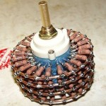
First of all, you need to get a rotary switch. It would be great if you can find something that does stereo and more than 20 positions. If you find something like that, great! If not, 11 position will do as well and I recommend the 11 position rotary switch made by Alpha that retails at only RM2.50. Cheap! (they look suspiciously like those USD40 Sweet Whispers from Bottle Head…)
Better still, you can be more macho and buy the ceramic rotary switch from www.kwtubes.com. Gintaras is a great guy to deal with! This rotary switch has 4 ceramic poles and the connections are all silver plated. Unfortunately, you need to drink lots of Tongkat Ali to turn this guy. Very tough! The tiny control knob that comes with it doesn’t help at all. In the end, I had to file off the peaks on the detent wheel and remove one of the springs. This helps A LOT. Access to a grinder is mandatory as filing manually will make MANY unhappy afternoons. This 11-position switch only cost me RM20, so you need to do some work. What’s a little work for us macho men??!!
And then, you can always go to Farnell or RS Components but do expect to pay a premium. Other options for rotary switch would be to salvage them from junk equipment. Oscilloscopes and the like always have some little treasures. I salvaged 3 pieces of nice Swiss-made Elma hermetically sealed 11-position rotary switch from some junk equipment before. Nice… Otherwise, you would need to spend big bucks on the likes of Elma, Goldpoint, DACT, Seiden… Ouch!
Wait a minute! Is 11-position enough? How comes those nice expensive switches all have 23 positions or more? Truth be told, you get what you pay for. Second thing is, it is my experience that you rarely use all 23 positions. You almost always use only half of them, so why not find out which half is useful then just use them! The 23 position is made for “general use”, and attenuation can go well down to say, -60dB. It really depends on your system. In mine, I find that -30dB is more than good enough. Remember! You are buidling this for YOUR system and not for “general usage”. You need to do your homework here!
Now comes to the second ingredient: resistors. Preferably metal film for lower noise and better frequency extension but I’m not going to tell you which to choose. If your favourite is Holco, Caddock, Vishay, Shinkoh, Riken, Kiwame blah blah blah, then use them. End of story. Likewise with solder. Take your pick from normal 60/40, 2% silver loaded, 4% silver loaded, eutetic, lead-free, pain-in-the-arse, whatever whatever whatever… Don’t blame me if the resistors cost a lot of money!
Alright! Let’s start work!
I prefer the simplicity of shunt mode so let’s use it. However, typical shunt mode has this problem of “break-before-make”. Refer diagram on left.
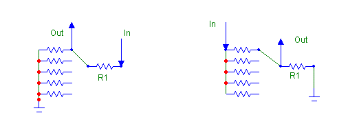
What I hate about the configuration on the left is that, when the switch is in between 2 settings, full output of your source goes through. Not a problem with mine as my amp is only 0.7W but it still gets very loud on 97dB speakers. If your amp is 100W, you may have to pick up your drivers from the floor!
Of course, if you are lucky to find those “make-before-break” switches, then you’ll be fine. Otherwise, a better solution would be to wire it in the configuration on the right. No harm done when the switch is caught in “no man’s land”.
All’s great now and here are some values of resistors. Remember you need to determine how much attenuation you need. These resistance work fine in my system but may not be so in yours. To determine how much attenuation you need is easy. With a multimeter, find the resistances where you listen to at max and at min. Calculate from there and this is the range you need to focus on. How to calculate? You always measure 2 resistance. One from input to wiper (call this Ra) and another from wiper to ground(Rb). To calculate gain, use
Gain = 20*log10[Rb/(Ra+Rb)]
Say you measured Ra is 90kohm and Rb is 10kohm, hence gain should be -20dB.
| 4700 | dB atten | diff | Vout | |
| 1 | 270000 | -35.335 | 14.507 | 0.034 |
| 2 | 47000 | -20.828 | 4.249 | 0.182 |
| 3 | 27000 | -16.579 | 2.167 | 0.297 |
| 4 | 20000 | -14.412 | 1.965 | 0.381 |
| 5 | 15000 | -12.447 | 1.435 | 0.477 |
| 6 | 12000 | -11.012 | 1.108 | 0.563 |
| 7 | 10000 | -9.904 | 1.135 | 0.639 |
| 8 | 8200 | -8.770 | 0.998 | 0.729 |
| 9 | 6800 | -7.772 | 1.751 | 0.817 |
| 10 | 4700 | -6.021 | 1.401 | 1.000 |
| 11 | 3300 | -4.620 | 4.620 | 1.175 |
The second column is how much attenuation in dB for this particular setting. The equation to calculate this is “=20*LOG10($C$2/(C3+$C$2))” where $C$2 is 4700.
Likewise, 3rd column calculates the difference between this setting and the previous setting. Note that I don’t care much going from -35dB to -20dB, but stepwise, reduced to ~1dB after that. Point is, the settings where you will see the most use, you should have those little 1-1.5dB differences. But hey, it’s your pot, so don’t listen to me.
The last column just calculates what if with a 2V input, what will the voltage seen by the amp. Equation to calculate this is “=2*POWER(10,D3/20)”
Note that my step sizes aren’t consistent 1dB every time as I just want to use standard size resistors. Too lazy to series or parallel them. If you want uniform 1/1.5/2dB attenuation, then you need to recalculate carefully. A simple Excel spreadsheet will do just fine.
