Rudolf Broertjes’ SS I/V Gain Stage
Greeings DIY brethrens!
Well ever since Monica conquered our hearts, there have always been questions from insatiable diyers asking for more more more!
Truth be told, Monica’s output is a little on the low side. Passive current-to-voltage conversion has its “beauty and beast” side. The beast side is of course current drive and low output. But the beauty… oh so beautiful… that I just feel that if we can’t find a suitable gain stage for her, then just let her be. Stay with this for now.
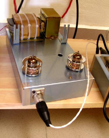
Then back in February 2006, CY “DAC Man” Liew shared with us his fabulous Grounded Grid Tube Gain Stage. If Monica sang before, now she’ll dance for you!
But DIYers will always be DIYers. Very soon, there were clamours for more, more, more again.
Then in February 2007, Ronald Verlaan shared on our forum this schematic by Rudolf Broertjes. Rudolf posted this schematic in diyaudio some moons ago.
Simple enough eh? The beauty of this circuit is that it sounds better than the vaccuum stage!
Plus you could power it at 12VDC though 18VDC is said to sound even better. For once, you could have your cake and eat it too!
I then contacted Rudolf but too bad he doesn’t have PCBs made for sale. I built a prototype and it’s rather time consuming. Besides without the benefit of a ground plane, noise issue etc could be a problem. So I requested Rudolf’s permission to build the PCB and sell to DIYers, especially Monica users.
And Rudolf agreed! So here you go.
Since this is not my design, and thanks to Rudolf’s generosity to share with all DIYers, I don’t want to profit from this. So the PCBs will be sold at a very low price, to cover costs, Paypal charges etc. You could order from our e-Store. http://store.diyparadise.com
Well, if that’s all to it, then it’s fine but I’m known to be a klutz many times. And this time is no different.
You see, when I built my prototype, for RSO1A, I used just a 82ohm resistor. And everything worked fine. Also, I couldn’t find any BF245A here so I went for the substitute of 2N3819.
As such, the PCB was designed for this.
When I got the PCBs in hand, then I realized a few things. Having a resistor instead of a trim pot for RSO1A is a BAD idea. Too many variations could give you problems. The LEDs’ forward voltage drop, transistor betas etc… All could affect the output DC voltage. Hence a few builds I did had output DC voltages ranging from 4VDC to 10VDC.
At 4VDC, Monica won’t sing at all. At 10VDC, she sings but off key (distortion!). This is why we want a trim pot! So to adjust output voltage to around half of VCC. So if you power her with 12VDC, then you want around 6-7VDC.
As such, there are a few mods we have to do here, no thanks to my clumsiness. Embarassing moments coming ahead…
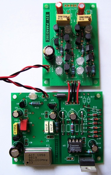
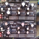
For RSO1A shown above, we have R7 and R11 on the PCB. Have to fit in a trim pot in a resistor’s place! Fortunately it’s not as bad as fitting in a square into round hole… or something like that. This is how you do it. Carefully bend leg 2 to leg 3 and solder them together. Then spread it apart so that it sits in the PCB holes nicely.
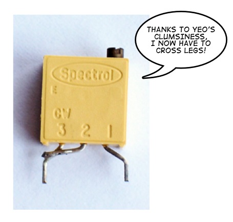
Now if you prefer to use BF245A instead of 2N3819, there’s a bit more work for you too. You see, the semiconductor world is full of crazy folks who don’t understand “standardizations”. Source/Gate legs on both FETs are reversed! So BF245A has to “cross legs” and wear “stockings”. That’s heatshrink for you!

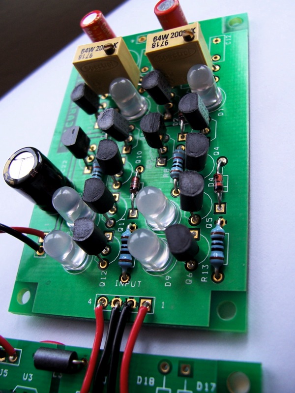
This is how it looks like. Shown here is for one channel only. Repeat for the other. My apologies again for this mess.

To integrate with Monica, this involves taking out components or if your soldering skills is suspect, just shorting them out. Err, either way you need to take out R19 and R20, then short the 2 inductors beside them all the way till C9 and C16. You could take out C9/C16 and use them at output stage of the I/V board and save yourself couple hundreds hours of running those darn Black Gates again.
A note about the LEDs. At first I tried those normal red LEDs but their forward voltage drop varies quite a lot between samples. In the end, I had to settle for these super bright red LEDs. They cost more but the forward voltage drops are pretty consistent. Only downside is you have to wear shades when playing music.
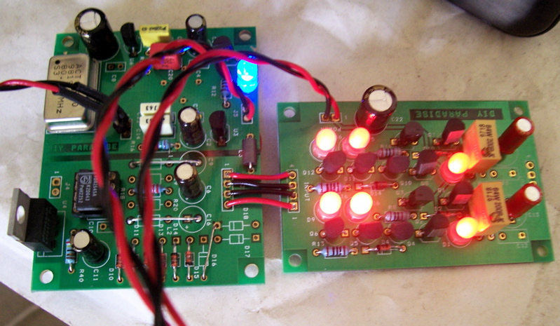
Okay, I exaggerated. 😀
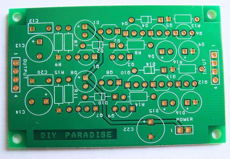
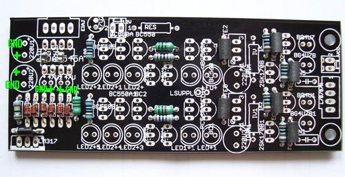
Building the SS I/V stage is very easy. Start off with resistors and diodes first.
R8, R14 — 820 ohm
R13, R16 — 100 ohm. Schematic above shows 270 ohm (RSI1) but as Rudolf himself said, 100 ohm sounds better.
R7, R11 — 200 ohm trim pot as shown above.
R9, R15 — is the critical I/V resistor. I recommend 3.3kohm if you use 12VDC supply. You could use bigger value with higher Vcc. Splurge on Kiwame, Holco, Riken, Shintoh… anything you like!
Next, we solder in the diodes. There are just 4 pieces of 1N4148 diodes. D2, D4, D10 and D14.
You could plug in the transistors now.
Q1, Q2, Q7, Q8 are all BC557.
Q4, Q5, Q6, Q10, Q11, Q12 are all BC547.
Q3 and Q9 are 2N3819s. If you prefer to use BF245A, then you need to cross its legs as shown above. Sorry again…
Now you can plug in those big fat LEDs. Be careful with orientation! + sign on PCB denotes LED anode – the longer of the LED leads. D1, D6, D9 and D8, D15, D16.
C13 and C14 of course is your output coupling capacitor. I recommend Black Gates N 4.7uF but you could choose anything you like. I left C12 and C20 blank but you could put in 1.1nF as shown in Rudolf’s schematic. Leaving it blank is good for now as we could measure across C12/C20 the output DC voltage.
Lastly C22 is the power supply capacitor. I use 220uF/25V Panasonic FM. Power input is labeled with pin 1 being the positive side.
Voila!
Upon power up, put your multimeter probe on C12/C20 and measure the output DC voltage. Adjust to around half of Vcc but it doesn’t have to be very accurate. I adjusted mine for 6.5VDC on both channels. I noticed couple minute upon power up, the voltages drift a little. Well, adjust again. After this adjustment, everything is fine.
I guess we are done now! Email or contact me if anything is unclear.


Hello,
May be you can help me understanding and fixing a defect of Monica3-usb. After weeks playing perfectly, I switched it on and heard a 100Hz hum in one channel and LEDD1 was not bright, and when switching off power, all LEDS of this channel lit up brightly for a moment, but all LEDs die much faster than normally (i.e. the PSU elco is drained quicker, indicating a high current in the output stage). I guess several transistors are blown. What could have caused this??? Too high PSU voltage? (18V)? Shorting of the output RCA (after the capacitor) while playing music? Leak currents from the laptop?
Best, Michiel
Hello I have build this output stage and it sounds very bright a has a lot off power/push. I want to add to this site that you should not forget R23. R23/47Kohm is not on the pcb so look out not to forget it.
That al Thank you’ll.
GJ Roossien
hi gj
thx for your comments. yes, r23 is not on the pcb. if you hook this i/v stage to a preamp, then the preamp’s input impedance is this “r23”.
let it run in and it’ll sound better over time. you could consider mojo too which is an improved ss i/v stage, from all the hard work of the diyers on the forum.
thx!
yeo