RM20 Non-Oversampling DAC project
Yeah! Believe it or not!
Heard all the hoo-haa over non-oversampling or zero-oversampling (what a mouthful) DACs? Would like to try one? For less than RM20? Read on!
If you have read the other article on this topic, you’ll know where to start. I’ll put more details here.
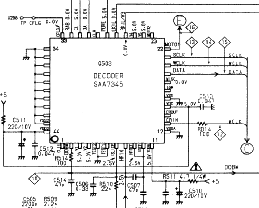
This the SAA7345 decoder in the CD63. Pay attention to 3 lines here, namely SCLK, WCLK and DATA (pins 21, 20 and 19 respectively).
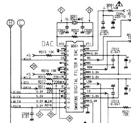
Digital filter and dac in the CD63. Note that the 3 lines from SAA7345, each go thru a resistor before terminating at at pins 8,9, & 10 of SM58728.
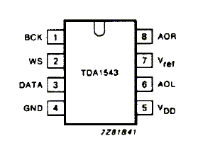
Here is pinout of TDA1543. What you need to do is wire SCLK to BCLK, WCLK to WS and DATA to DATA pin. Yup, just 3 wires. Easy huh?
What else do you need? Obviously power supply and output connections.
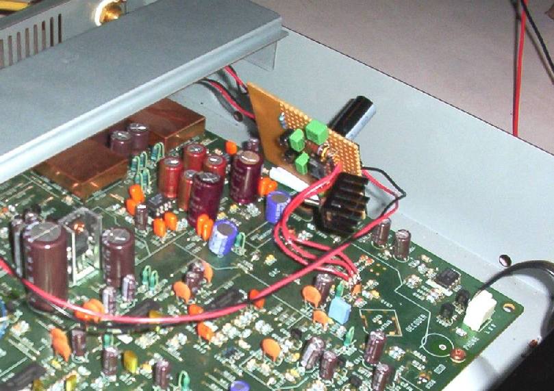
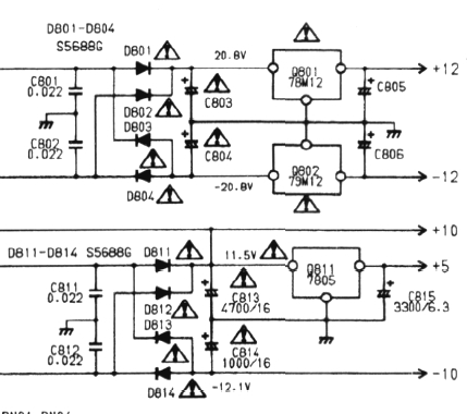
I tapped the supply from capacitor C803. It’s about 20V here. This involves taking out the player PCB of the CD63. Hope you are comfortable with this. ; )
Know where to start? First wire the power supply first. Bring 2 wires out from +ve and -ve terminals of C803. While you have the player PCB out, desolder one end of the resistors RD11-13. Desolder the end nearer to the SAA7345. Reason for desoldering it is to lift out the leads slightly higher. Then solder it back. Without interrupting its present function, we now can solder wires on the “lifted resistor lead”.
Put the player PCB back in and solder the wires of the power supply to the 7808. Note that I drew LT1085 in the schematics. That’s because I used SwitcherCad to draw this circuit. Feel free to use any regulator of choice. With 8V, the TDA1543 is running very hot so you need heatsinks on them. Once you have wired up the regulator, you can start work on the signal lines. As the 3 I2S pins from the SAA7345 are only capable of 1mA current each, so it’s sensible to keep this wire as short as possible (mine is about 5cm from the resistors). Tin the “lifted” resistor ends of RD11-13 with some solder first. Then solder the 3 wires from TDA1543 to these ends, paying attention which goes to which. Refer schematics.
Output is straight forward. Run 2 line from Analog R/L channel and a third Ground line to output RCA jacks. I intend to drill holes on my PCB to accomodate these sockets thus I have a choice of 2 different types of sound from one CD player.
That’s it! Your RM20 DAC! Signal level was initially very low with a single TDA1543. But with some help from vt4c, I changed the I/V and bias resistors and now it’s okay. Here’s a few configurations you can play with.
1. power supply at 8V AND parallel 4 pieces of TDA1543. With this configuration, change I/V resistor to 680 ohm and bias resistor to 330 ohm. 7808 gets really hot. You need bigger heatsink on it, and the 1543s. Everyone of them.
2. add a gain stage to the output, either using opamps or tube output stage. You COULD import the whole 5687 preamp stage here.
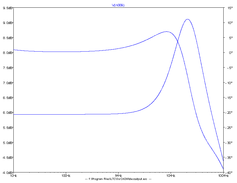
Note that the below the 1k I/V conversion resistor, there’s a parallel resonant circuit. It’s meant to bump the 20kHz by ~3dB as this non-oversampling DAC circuit’s frequency response is 3dB down at approximately 20kHz. Simulated response is as shown below. Bottom trace is magnitude trace. It stays flat all the way till 10kHz, starts to rise and peaks ~3dB at ~23kHz. Upper trace shows phase. Stays flat all the time but off by 5 degrees at 20kHz. If this bothers you, remember your speaker has much wilder phase shifts. : )
At the moment, still letting it run in but so far, find the sound, not as smooth as the internal DAC of the CD63 but my oh my! The midrange is especially vivid! Current favourite is Willie Nelson’s Stardust. I seem to hear more echo/reverbaration in his voice. Sounds a lot more life like! At RM20, it has no reason to sound so good!
Update on April 15, 2003. Great reading here. An Interview with Kusunoki San, initiator of non-oversampling DACs theory
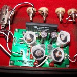
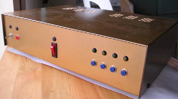
Update on May 5, 2003. Believe it or not, this ugly contraption makes good music. ; )

No Responses