A step-by-step with photos for newbies…
How to build your own tube preamp
Alright, I have introduced a few simple projects. Now, let me show you step-by-step (almost) how I built one. I’m refering to the circuit explained on 5687-based Simple Preamp. Schematics is repeated here.
Okay, before class begins, pre-requisite knowledge is:
1. You got to know your resistors and capacitors. Yes, if you can’t tell a resistor from a capacitor, ask knowledgeable friends or pay a visit to Jalan Pasar.
2. Know what is a choke and what is a transformer.
3. Directly related to 1 and 2. Know what the symbols mean on the schematics below.
4. Know how to solder.
5. Able to follow simple instructions. Once your preamp is singing, you can mod to your heart’s content, but for now, let’s follow instructions, okay?
Okay! Let’s start!
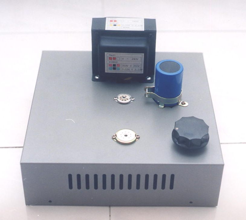
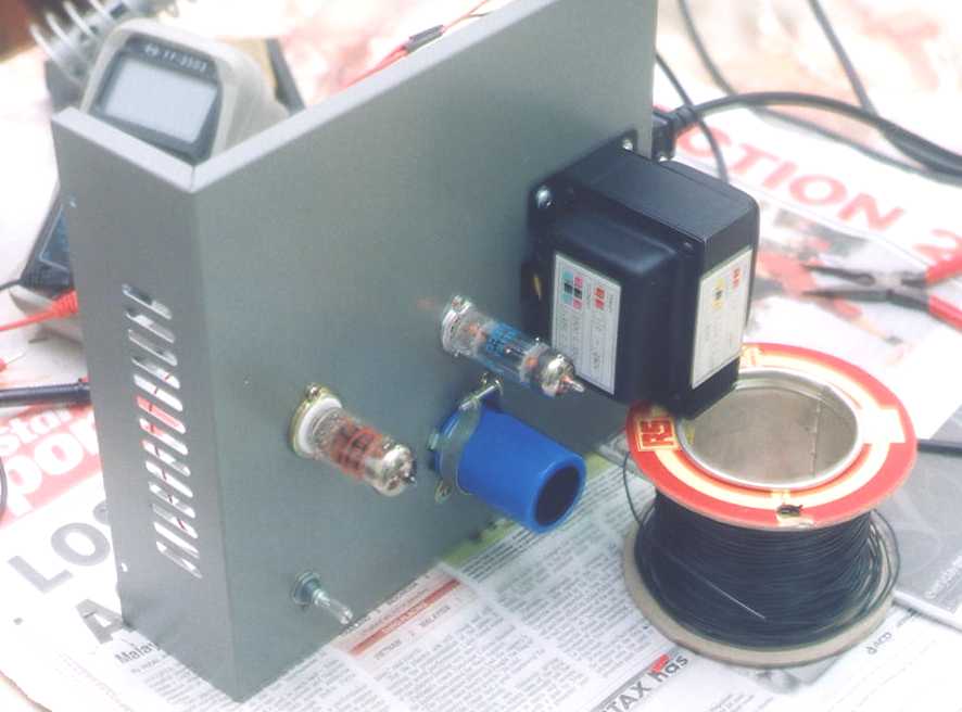
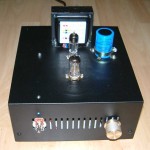
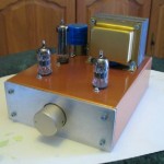
We begin by first drawing the layout on paper, how are we going to lay the components out. We need to decide where does signal come in, and where does it go out. For simplicity, I’m using a piece of metal, folded at the ends, so it forms a huge upper case ‘C’. Components will be layed on the top plate. Back plate holds RCA jacks and IEC socket. Front plate is left blank. Click on preamp picture to open up this power point file.
Okay, study time. Please go through the schematics, wiring drawing and tube base configuration in the ppt file. Print it out if you have to. Can you understand how is this preamp wired? It’s important to understand the ‘whys’ now. Please be accountable for every wire there!
If you now understand the wiring, then comes the implementation.
Step by step we’ll go…
The power transformer is specified as one primary and three secondary tappings. Primary is 240-0V and secondaries are 350-0-350V@100mA and two secondaries of 3.15-0-3.15V@2A. The 3.15-0-3.15V secondary is to provide 6.3V to the heaters but there is an option to use the ‘0’ tapping to either reference it to ground or reference it to some elevated voltage. You want to do this as there is a limit to the potential difference between tube cathode and heater. If you exceed this limit, unneccessary stress is placed on the tube and it’ll fail in a shorter lifetime. Thus, if your cathode sits at 100V, then it’s a good idea to reference your heater to ~100V. In this preamp, I have referenced both heaters for 5687 and 6X4 to ground as cathode of 5687 is only 5V and though cathode of 6X4 is at ~250V, the datasheet says that it can take up to 450V, so that’s okay. You can of course, choose to reference the heaters to some other voltage.
Boring eh? Well, you need some photos! Read on!
How to build your own tube preamp Part 2
If you have done your homework, you should understand how it’s wired up by now. Nevermind, here are some photos to help you.
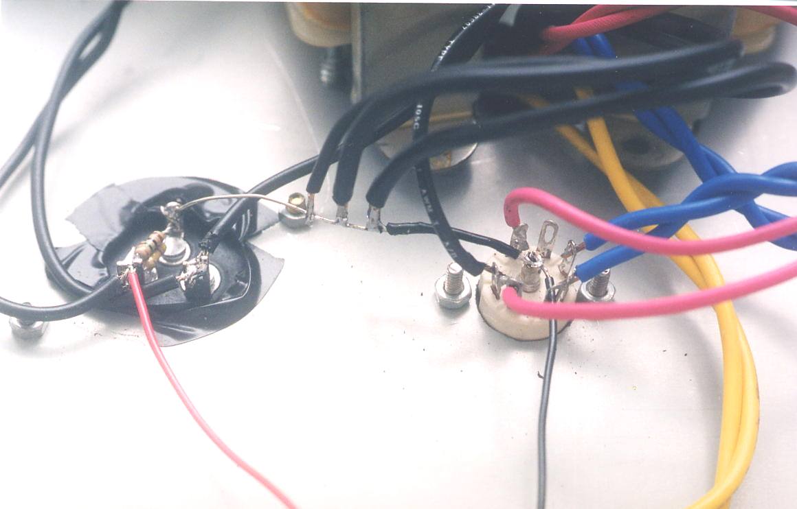
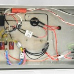
You start by laying out the ground path. I used the same wire as the rest here, but you could opt for the better option of using thick copper, say awg 12. A good and cheap option is those copper rods used for gas welding, available from your local hardware store.
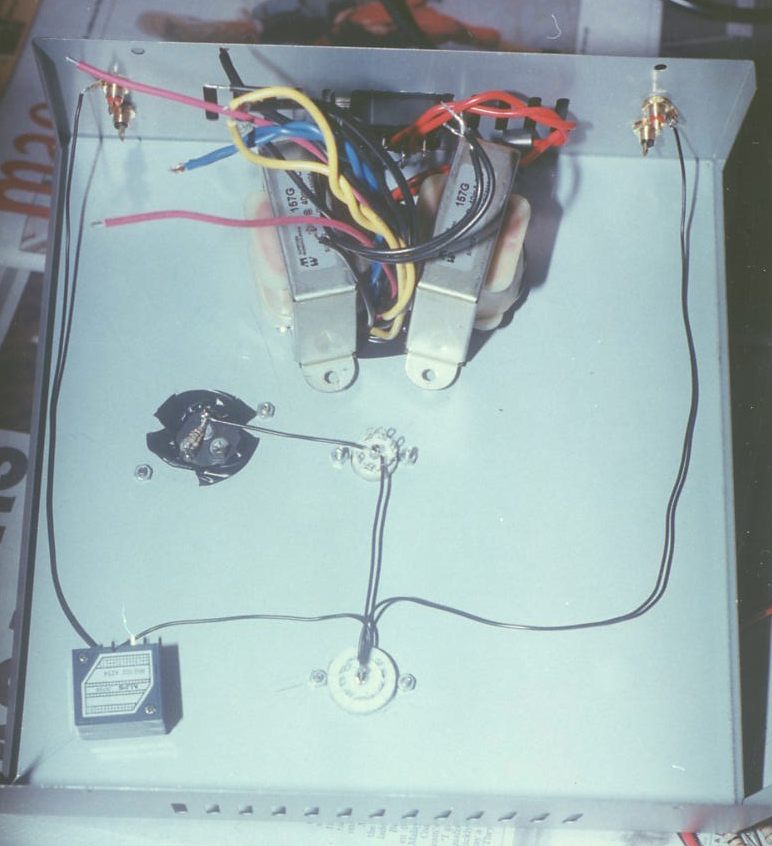
Here, the filament wires have been wired. This is simple as there’s only 2 tubes to consider. Note that I have wired 5687 heaters in PARALLEL. That means shorting pins 4 & 5 and wiring heater to 8 and 5. All filament ‘0’ tap refered to ground.
Next, I wired up the power supply section. It’s easy with this double capacitor. The pink wires are 350V. The red wire coming out from the capacitor is my B+. Note that I have wired in a resistor on the capacitor. This goes from +ve to Gnd. This is a bleeder resistor, meant to discharge your capacitor’s charge, lest it discharges on YOU with dire (some find it fun though) consequences. Aim to bleed about 1mA, so for B+ of ~280VDC, a bleeder resistor of 270kohm/2W is fine.
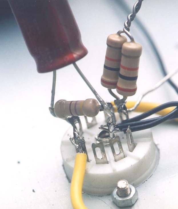
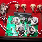
Ahem, signal circuitry. Remember signal circuitry consists of only 2 resistors? One on the plate and one on the cathode? Here the plate resistor is a paralled combo of two 20kohm 2W resistor to give me a 10kohm 4W resistor. The cathode resistor is 470ohm, paralleled with a 470uF electrolytic. It’s better if I could place the electrolytic lower but this makes it easier for modifications later. Being DIYers, this is important! Err, shown here is only signal circuitry for Left channel. Yellow wire is for filament heater.
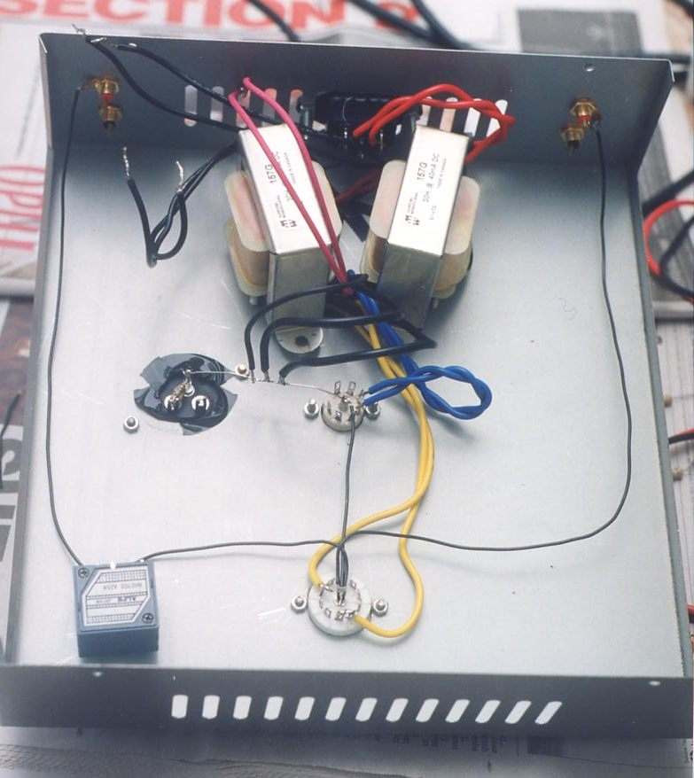
While you are enjoying the pictures (and waiting eternally for them to download…), I have finished wiring up the other channel! Click for higher resolution (and more waiting) picture.

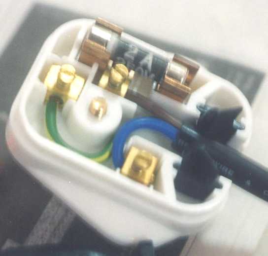
Okay, the urgency to power on is high now but hang on! First thing first, before you plug in your IEC cable, change the fuse in the plug to a lower current rating. I have 2A here as I can’t find 0.5A. Preamps don’t need high current so 0.5A is good enough. The last thing you want is for some fault to occur and your nicely built preamp go up to smoke just because the current isn’t high enough to break the 13A fuse. You have been forewarned!
Another use of a wire spool… This way, I could test the voltage points with a multimeter. It’s important to make sure voltages are correct within 10% tolerance before plugging into your system. Check with voltage points on the schematics.
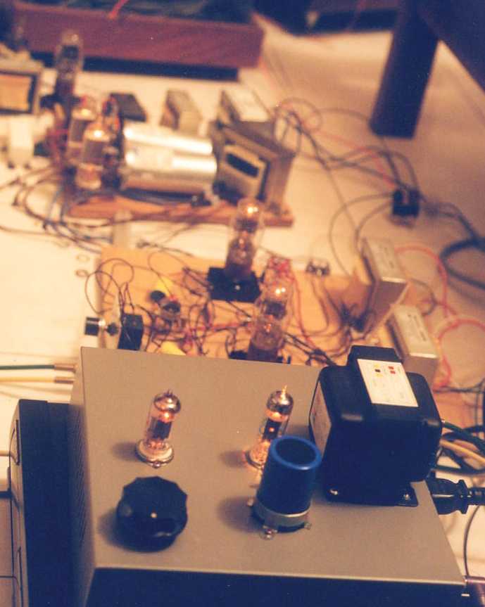
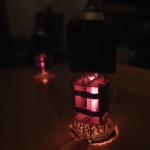
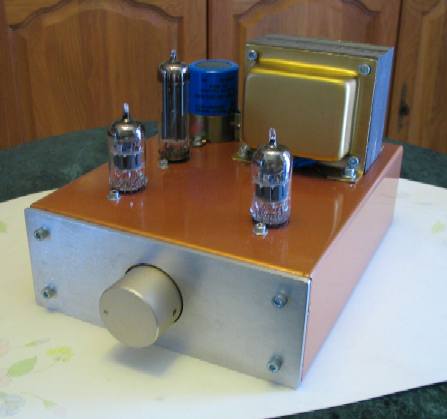
Finito! Bathed in warm light as well! No wonder it sounds warm?
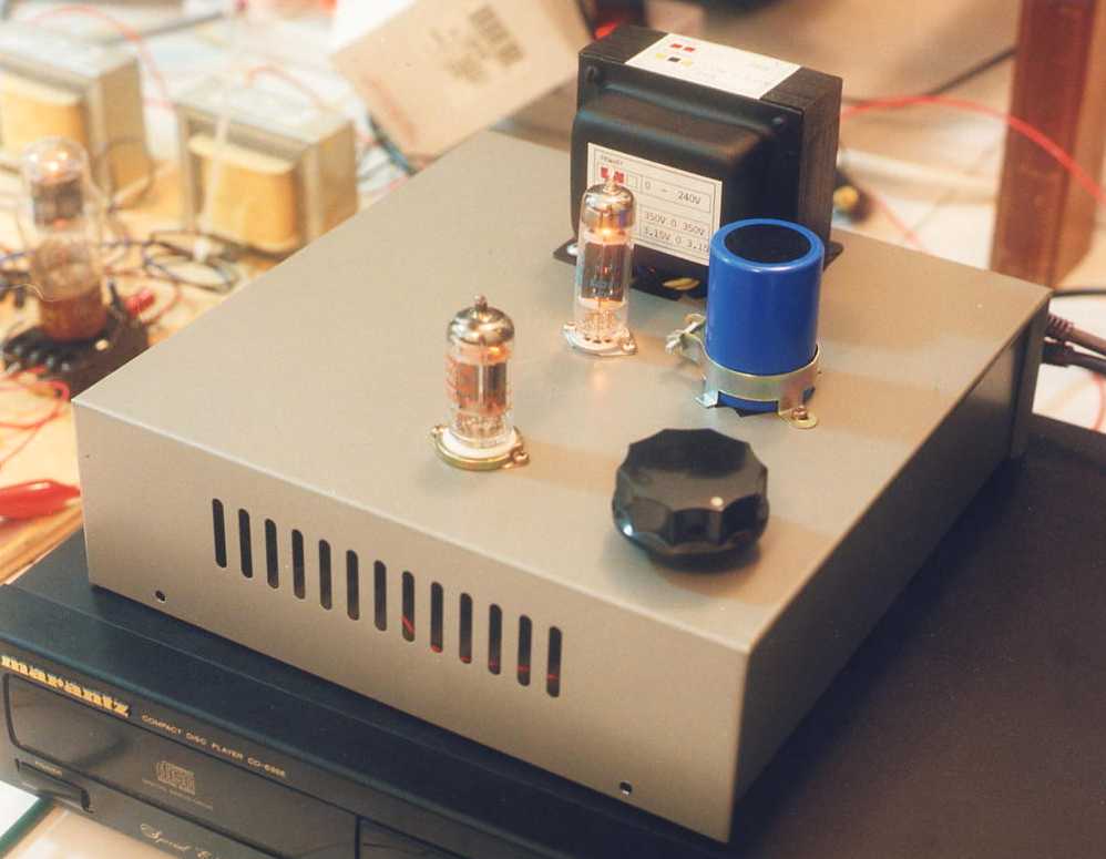
Plays music with the rest of the system. It worked right the first time!
There you have it! Hope you enjoyed the music, err the ride. Sorry for the long download time.
Done yet? Not yet!
How to build your own tube preamp Part 3
This is basically an options page.
The fun of this preamp doesn’t end with its completion. In fact the fun has just begun!
Even if you haven’t built this preamp, it’s good to take a look here to see the options ahead of you.
Power supply. You don’t have to follow my power supply circuit. I like chokes but it’s okay if you hate them. You can build it ala Audio Note or your own design. Your own design? Yeah, why not? It’s not that difficult. You can use Duncan Amp’s excellent Power Supply Designer. This simulator is highly recommended. Includes tube rectifier as well! Only snag is: you don’t know how it sounds. Anyway, with some idea what is the B+ needed, try different combinations and build different circuits and see which sounds better to you. There’s solid state diodes to play with, different tube rectifiers, capacitor input power supply filter, choke input…
Operating point. This 5687 has plate voltage of ~140V at 11mA. You can go higher, or lower with just a change of resistors here and there. You’ll get different sound, for better, for worse, try it and tell me!
Coupling capacitor. There are choices here rather than just the 0.1uF of Audio Note’s circuit or 0.47uF of vt4c’s circuit. The function of this capacitor is to block out DC voltage and allow AC signal to pass through. With the succeeding resistor to ground, it forms a high pass filter. Knowing the input impedance of your power amplifier that you are going to connect to this preamp helps you determine which coupling capacitor you can get by.
freq = 1/[2*pi*R*C]
Remember the above formula. Because taking R as input impedance of the subsequent stage, then… nah, this is too much to explain. Look at the table below. I have calculated the bass frequency cut-off using a combination of R and C. The R refers to input impedance of the next stage paralleled with your 1M resistor (which would come up pretty close to the next stage input resistance anyway). The C refers to coupling capacitor at output of the preamp.
| R in kohm | C in uF | freq | C in uF | freq | C in uF | freq | C in uF | freq | C in uF | freq | |||||
| 50 | 0.1 | 31.83 | 0.22 | 14.47 | 0.33 | 9.65 | 0.47 | 6.77 | 1 | 3.18 | |||||
| 100 | 0.1 | 15.92 | 0.22 | 7.23 | 0.33 | 4.82 | 0.47 | 3.39 | 1 | 1.59 | |||||
| 250 | 0.1 | 6.37 | 0.22 | 2.89 | 0.33 | 1.93 | 0.47 | 1.35 | 1 | 0.64 |
What’s the point of knowing all this? So that you can be cheap! If your power amp has input impedance of 100kohm and you find coupling capacitor of 0.47uF to be too expensive, look at the table… this combo gives a cut-off of 3.39Hz. Well, if you don’t mind the cutoff at 7.23Hz, then you could use 0.1uF! After all, can your speakers produce THAT low? The point being 0.1uF is cheaper than 0.47uF of the same voltage rating. Okay, enough talk, try your hand at being ‘cheap’. 🙂
Resistors. Try any type you like! Carbon, metal, Kiwame, Holco, Vishay, Caddock, Chinese firecracker, cap parang… see I told you you could mod to your heart’s content. Just observe power ratings. Plate resistor of 10kohm has to be rated for at least 2.5W while you can get by with cathode resistor 470ohm of 1/2W.
Electrolytics. In the power supply, and cathode bypass of 5687. Use whatever you like.
Actually, my parts philosophy is very simple. Build it with whatever cheap components you have. Build it first, get it working first THEN mod it and substitute with whatever audiophile-approved, boutique, space-age, friends-claim-to-be-best-sounding part. Blindly using audiophile parts without regard is like cooking without knowing what spices you are using.
Wire. Yeah, some say solid core sounds better, some swear by stranded Litz, some prefer copper, some silver, Teflon insulated blah blah blah… Take your pick. For simplicity, I’m using cheap 600V solid core tinned copper of 22-23AWG. Try whatever you like. Just be sure to observe voltage ratings.
What next? How about a hint? This is a tube preamp… Yeah! Tubes! Here are some choices.
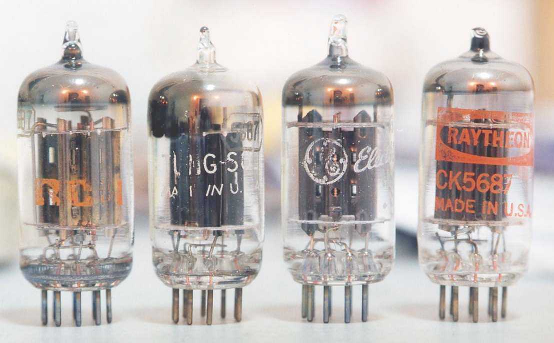 RCA, Tungsol (sold out), GE & Raytheon.
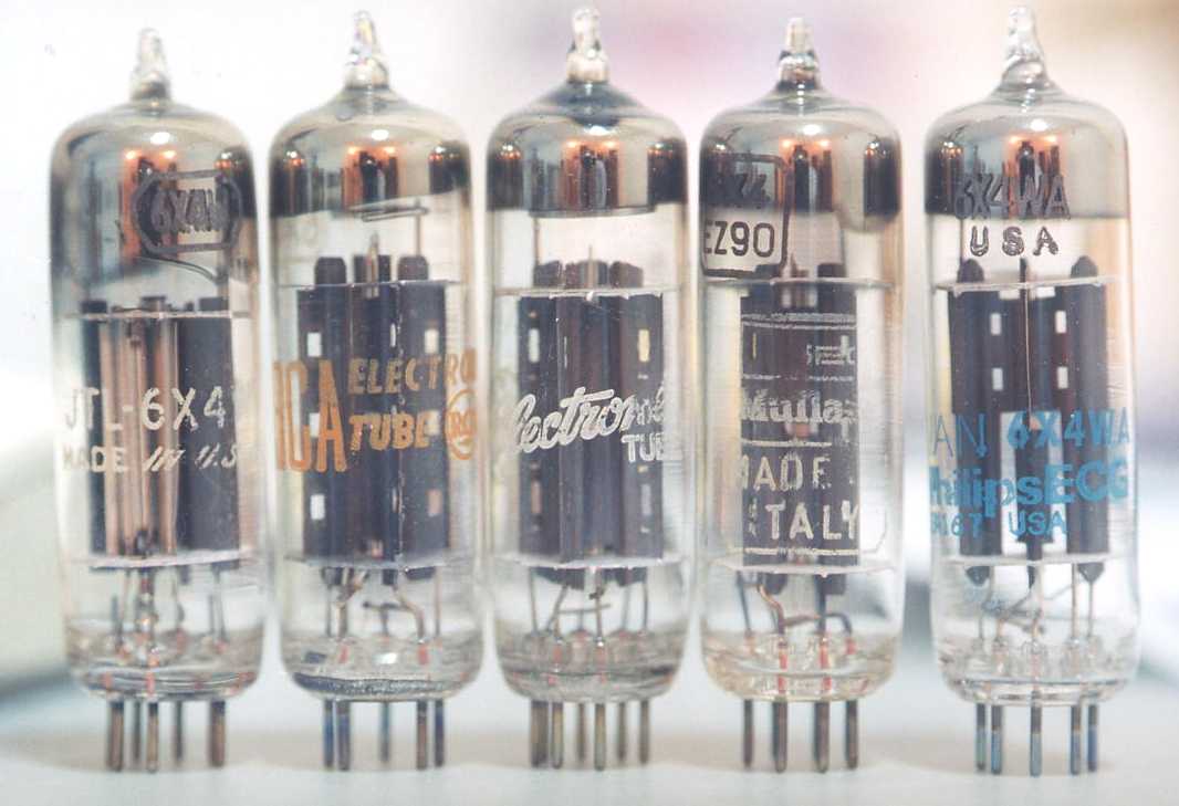 Tungsol, RCA, GE, Mullard (not avail) & Philips JAN.
Okay, I’ve done enough. It’s time to enjoy my music!
I said that too soon. Here is a FAQ page.
Hello, I was wandering what transformator you are using, is it a Hammond and if so what type. If not what type can I use from Hammond. Thank u very much.
Andy from Belgium
😮 That is mission impossible
i cant open the wiring diagrams! Could some one please forward to my email add ? thanks!