Cloning Monica
Well, well, well, since her debut, Monica, and subsequently Monica2, has been so well received by so many audio enthusiasts worldwide that if you haven’t heard of her, you better get out from your cave! Inevitably, success brings its pitfalls. The obvious being :
1. being zapped out of life. Yeah, I have no life these days, quietly soldering and soldering, fulfiling the sonic hunger of audio enthusiasts all over.
2. I feel so good, so inspired, whenever I receive emails thanking me for such a wonderful piece of audio equipment! Well, as the cliche goes, Monica is MORE than an audio equipment. : )
3. Time and time again, I have found her jiving with gears costing more than 20x her selling price! Just proves what an amazing value she is. No wonder you guys are so in love.
4. I get so many veiled attempts at finding out how I build my baby. How I “inject” pixie dust and create music magic. Seems like quite a number of folks intend to CLONE Monica.
Oh well, since you try so hard to “dig” info out of me (short of sending the mafia to my door), let me come clean with you. If you want to clone Monica, at least do it right.
In this context, I define the “cloning” of Monica as utilizing the TDA1545A dac chip in similar configuration. Note that I don’t run TDA1545A per the datasheet. I use 2.2kOhm for the I/V resistors, 22kOhm for the Vref resistor and bias this pin at 1/2VDD. Nothing scientific but definitely different from the rest.
So if you want to clone Monica, at least do it right!
PCB
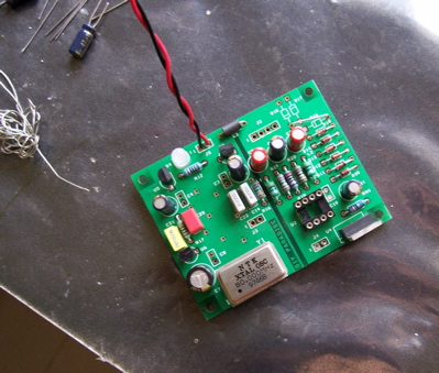
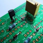
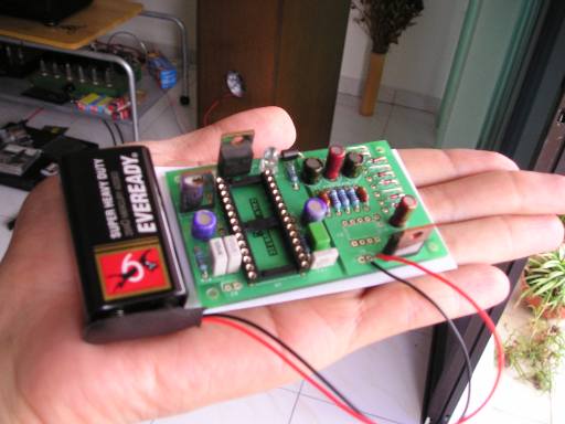
Needless to say, very critical component here. First started out with silver plated PCB but then switched vendor due to inconsistent quality problem. Current PCBs are all GOLD plated. We do this mainly for lead free reasons so that our European brothers and sisters could enjoy Monica’s magic too. You could say another reason is more “selfish” so that I breath in less lead in the solder fumes and won’t be so stoopid in the long run. You know what folks say about lead damaging our brain etc et etc? You know, me doing silly things like selling Monica too cheap. : )
Double sided with the top layer being one huge ground plane. Single side PCB just won’t cut it ok? Beside every electrolytic, there are provisions for you to solder in a small ceramic bypass cap for more effective power supply bypass.
Components
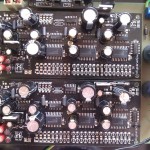
Digital circuitry is less fussy but eletrolytics are best with Low Impedance caps. I started with Sanyo Oscons but due to availability problems, then switched to Panasonic FCs and FMs. I find them just as good with insiginificant sonic difference.
The regulators are just basic 78xx series type. Nothing special I know but listening tests with shunt regulated types didn’t yield that much sonic difference so… why bother? More importantly 3 separate regulators are used for the digital receiver’s digital/analog circuitry and the reclocker circuitry.
On the analog side, caps have come and gone but only one cap, I will NEVER change (until I can’t source them anymore). And this is the non-polarized Black Gates N series 4.7uF 50V at the output. Have compared them with couple of polypropylenes etc but these little BG beat them all in terms of TRANSPARENCY. Well, size as well, ha! It is my aim for my audio gears to sound as transparent as possible, never interfering with the music. Meaning, the equipment does not get in the way of the music. You could try other caps, of course, but this will be your sonic preference, not mine. Entirely up to you here.
The power supply circuitry consists of a constant current source feeding a shunt regulator. The LM317 and resistor sets the CCS of 50mA while the series diodes form a shunt regulator. All this to regulate 5V. Absolute 5V is not critical but absolute stability is. As TDA1545A draws only 5mA max, the regulator combo only has to cope with 10% variation in its current. Such an easy job! It is for this reason that the power supply filtering is very clean here. Very nice. So much so that all the details in your music comes through unhindered. If it’s there, Monica will sing for you. She’s a great gal!
I once offered standard Black Gates for the power supply bypass beside TDA1545A. Not necessary at all as simple Panasonic FCs do a great job here. So don’t get too hung up on the Black Gates name. Not all of them are gold. The standard stuffs are really no big deal. Reserve your respect for the BG N series!
Other nifty details
Well, TDA1545A uses low profile sockets – which costs more but sounds better.
The PLL filter caps, it’s imperative to use polypropyelene for the 3300pF cap.
We love Monica when she sings with 80MHz oscillator.
The flip flop chip has to be ACT series or higher. With ACT, it’s good up to 125MHz. DO NOT USE the much cheaper HC and other slower series.
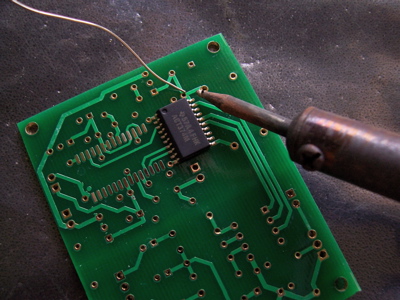
Only lead free solder is used throughout.
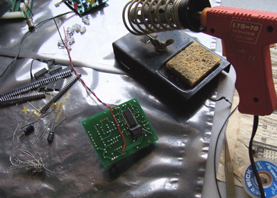
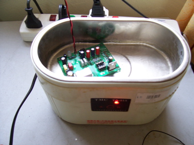
Assembly
There you go. I hope you learned something about how I build Monica. You guys who want to clone Monica, I hope you find something useful here.
Thanks and enjoy your Monica!
