Some folks call it Balanced Power Supply. Learn how to build one.
Searching for Clean Power
Experiments with powering Charlize (and then Charlize2) showed what a big sonic improvement different power supplies could bring.
Thus, I was trying the same with Monica3. Tried various switching power supplies, built a linear supply, built/evaluated/listened-till-ears-bled up to 3 types of regulators but I’m still unhappy.
Sure, Monica3 never fails to bring a smile to my face but I want More! More! And More!
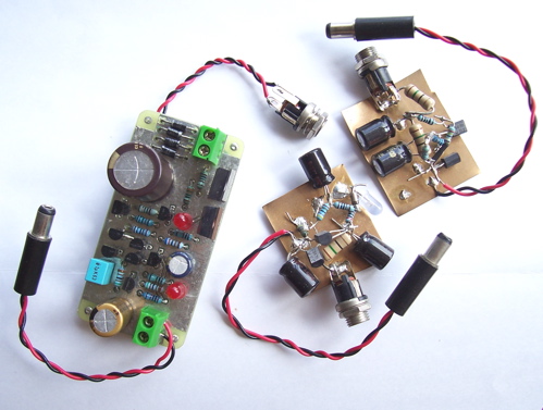
Just when I thought I should build more regulators and listen and evaluate some more (and in the process lose my sanity as well), a DIY friend showed me this link. MT Audio Design’s MF-2001".
Now from time to time, I’m always exposed to some really interesting ideas, thanks to the wonderful World Wide Web, but never had the luxury of time to build/execute/listen to these wonderful ideas. But since I’m working on Monica3’s power supply, I thought why not give it a try. After all, the idea is so simple yet makes so much sense!
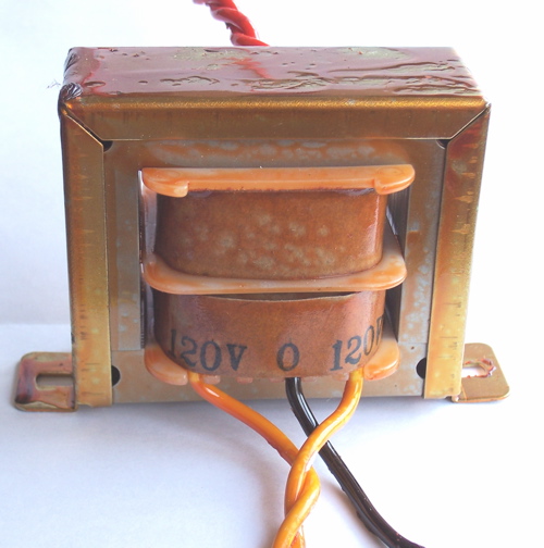
Thus I got the trans wound. Note that this is a double bobbin design. More on this later.
And built a linear 24VDC supply for Monica3. I’m aware that the caps on Monica3 is only rated for 25VDC but my own Monica3 I have let her run at 25VDC for more than 6 months now and she’s still singing happily. The LM317 chip deserves a bigger heatsink though.
Now, this time, did I jive? More than that!
I was totally taken aback by how good this thing is! Flabbergasted! Smoking Catfish, this thing smokes!
Not only it expectedly cleaned up noise in the background, now I could play much louder than before and the system does not struggle with complex music any more. For example, when listening to choirs, with many voices singing simultaneously, it used to be hard to follow every individual voice, but not now! I even dared demo Carmina Burana’s "O Fortuna"!
This is so powerful I could even "see" into the details. When listening to one choir, I found myself saying,
"Hey you, kid in third row, fifth from left. I could hear you skipping two syllables. And when you sing, stand still! Quit swaying around!"
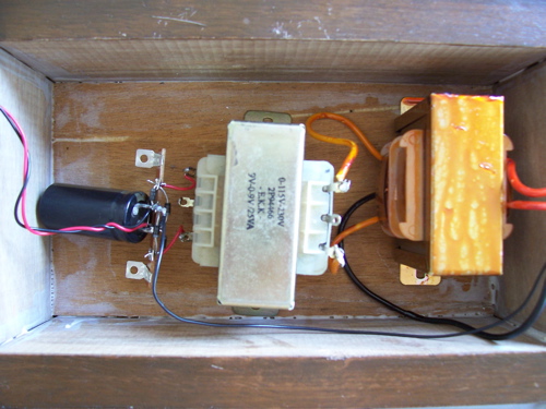
Ok, ok. This is what I built. Note that I didn’t even install any EMI/RFI filter at the input. There’s no regulation for 24VDC so I’m relying on the onboard regulators to work its magic. Both trans are specified as 30VA.
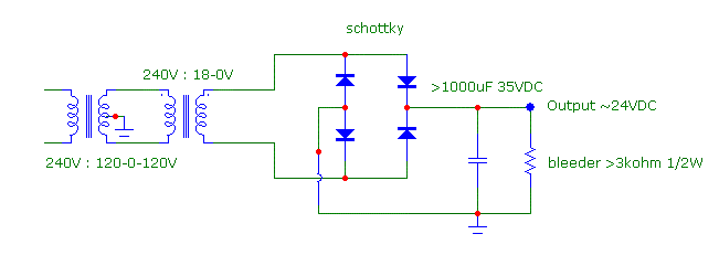
The key here is the first transfomer, the isolation transformer with a center-tapped secondary. I asked for 3 magic spells from the trans winder genie and this is what she gave me.
First, the trans took up any DC current prevalent in the mains supply, thus shielding it from the second trans.
Then with its lousy bandwidth (EI cores using "normal" grade iron), it is a noise filter. The fact that it is a double bobbin helps out even more. You see, usually the secondary windings are wound on top of the primary winding in a trans, usually separated by paper, but you can’t discount the possibility of mains stray noise coupling to the secondary.
With a double bobbin design, the primary is wound on one section of the bobbin, while the secondary is wound on another. Noise coupling between the two is greatly minimized. See how good an idea this is? I went the whole nine yards and had both trans wound double bobbin.
Thirdly, and this is the most important feature here. Common mode noise is filtered away due to the center tapped secondary. Now noise is, to some extent, easily filtered via capacitors and inductors etc but common mode noise is tough to beat as it’s "common", meaning it’s "everywhere". It’s prevalent at both legs of the transformer secondaries you see. Thus with the center tapped there, they both see a low impedance path to IEC Earth and thus "filters away".
Have I lost you yet? I hope not!
Anyway, this idea isn’t new. A search on Google shows many variations of this scheme with fancy names like "Balanced Power Supply" etc. As you can see, it’s nothing more fancy than just an isolation trans with a center tapped secondary. Well, add some EMI/RFI filters if you like.
What? Can’t find such trans? Well, the below version uses off-the-shelf transformers wired back-to-back. You could use 9-0-9 or even 12-0-12 as long as both trans’ are the SAME. The principle is just as sound but may work better due to even more levels of filtering. The optional capacitor provides an even lower impedance path for noise. Read this somewhere ago.
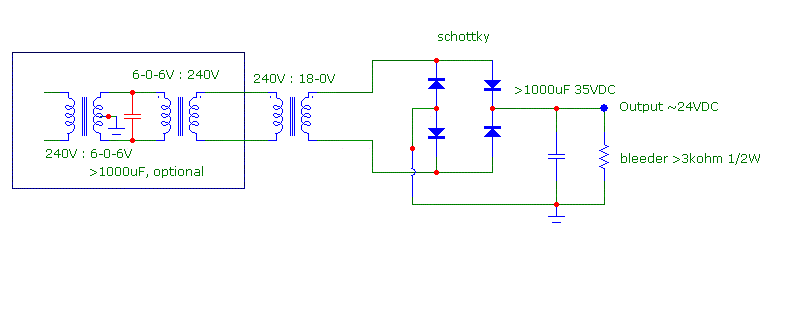
There you have it! Some simple and yet so effective. If you are macho, you should build one each for every gear in your system. One for CDP, one for DAC, one for preamp… Need to size the VA accordingly.
Feel free to build one yourself but if you can’t, let us build for you!
We even thought of a good name for this product. In line with our penchant for naming minor products after rock bands, you can’t go wrong with AC/DC!


testing
Where is the 3rd transformer in your photo ?!!
Putting a large-valued cap across 50Hz or 50Hz AC will cause it to draw LARGE amounts of completely wasted current (==> power). The larger the cap is the larger the waste will be. You really want a SMALL, low-inductance, low-ESR, high frequency, non-polarized cap to filter out any HIGH FREQUENCY noise.
The transformer’s winding’s polarities are POINTLESS! We’re dealing with A/C.
The min size of the output cap and the bleeder resistor are completely dependent on the max current drawn from the supply *for a desired minimum amount of voltage ripple*. The values are proportional to the max output current drawn by a particular application.
Using 3 transformers instead of just 1 will drastically reduce the max power output of the supply. Assuming 85% transformer coupling efficiencies, the max output of 3 # 50 volt-amp transformers will be only 50VA x 85% x 85% = 36 volt-amps. (The effic. drop from the first xfrmr has been accounted for.)
Post link to product 😥